Ambient Air Temperature Sensor, Checking
Ambient Air Temperature Sensor, Checking
Special tools, testers and auxiliary items required
• multimeter.
• Wiring diagram.
Test procedure
- Perform a preliminary check to verify the customers complaint. Refer to => [ Preliminary Check ] Preliminary Check
Start diagnosis
- Connect the scan tool.
- Engine MUST be at room temperature.
- Switch the ignition on.
- Using the scan tool, check the ambient air temperature:

If the specified value was obtained:
- Fault may be intermittent. Check for proper connection, damaged wiring or loose terminals.
• The reading will default to 419 °F if the circuit is open or shorted to ground.
If the specified value was Not obtained:
Checking internal resistance
- Turn the key off.
- Disconnect the Ambient Air Temperature Sensor (G17) electrical harness connector.
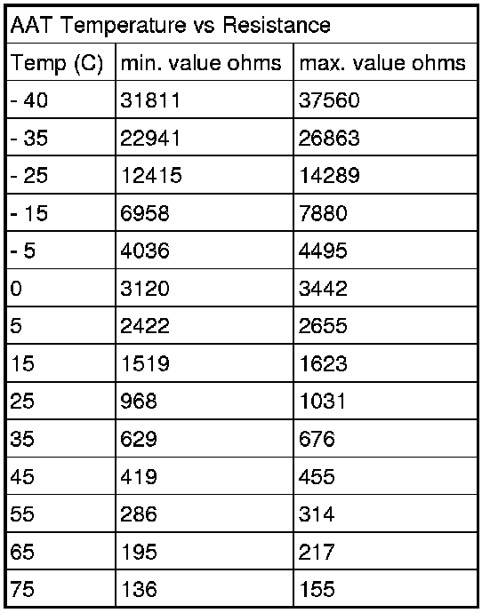
- Using a multimeter, check the Ambient Air Temperature Sensor (G17) terminals 1 to 2 for resistance.
Use the chart below for the specified values:
Specified values:
If the specified values were Not obtained:
- Replace the Ambient Air Temperature Sensor (G17). Refer to the appropriate service manual.
If the specified values are obtained, continue the test according to the following table:
Checking wiring
- Turn the key on.
- Connect a multimeter to terminals 1 and 2 of the Ambient Air Temperature Sensor (G17) electrical harness connector.
Specified value: near 5.02 V
If the specified value was Not obtained:
- Turn the key off.
- Remove the Instrument Cluster. Refer to the appropriate service manual.
- Disconnect the Instrument Cluster harness.
- Using a multimeter, check the Ambient Air Temperature Sensor (G17) electrical harness connector terminals 1 and 2 to the Instrument Cluster electrical harness connector T36 for an open circuit or a short, refer to the appropriate wiring diagram.

Specified value: 1.5 ohms max.
If the specified value was obtained:
Replace the Instrument Cluster. Refer to the appropriate service manual.
If the specified value was Not obtained:
- Check the wiring for an open, high resistance or short circuit to Battery (+) or ground.
- Check the electrical harness connector for damage, corrosion, loose or broken terminals.
- If necessary, repair the faulty wiring connection.
Final procedures
After the repair work, the following work steps must be performed in the following sequence:
1. Check the DTC memory. Refer to => [ Diagnostic Mode 03 - Read DTC Memory ] Scan Tool Testing and Procedures.
2. If necessary, erase the DTC memory. Refer to => [ Diagnostic Mode 04 - Erase DTC Memory ] Scan Tool Testing and Procedures.
3. If the DTC memory was erased, generate readiness code. Refer to => [ Readiness Code ] Readiness Code.