Evaporative Emission System Monitoring
Evaporative System Monitoring
(E36 TLEV Vacuum system)
All criteria are subject to modification and addition for future requirements. Refer to future amendments of section 1968.1 of Title 13, California code of regulations entitled "Malfunction and Diagnostic System Requirements - 1994 and Subsequent Model - Year Passenger Cars, Light Duty Trucks, and Medium Duty vehicles and engines (OBD II)."
Reference: www.arb.ca.gov/msprog/obdprog
Malfunction Criteria:
TLEV: The system is considered to be malfunctioning when:
- No purge air flow can be detected (Oxygen Sensor Feedback), or
- When a leak is detected in the system that is equal to or larger than 1 mm (0.040 in.).
The monitored components include:

Monitoring Conditions:


Before the Evaporative System is tested, the following conditions must be met:
- No faults currently present for:
1. vehicle speed,
2. engine coolant and/or intake air temperatures,
3. idle speed,
4. oxygen sensors,
5. purge valve,
6. fuel tank pressure sensor,
7. evaporative emission canister shut off valve,
8. throttle position.
- Engine coolant temperature must be > 80° C
- Current altitude < 2500m (8,202 feet).
- Accumulated Canister Purge time > 360 seconds (6 minutes) since start of drive cycle.
- Canister purge cycle times between 10 and 150 seconds in length (dependent on HC saturation).
- Vehicle speed (V) = 0 (vehicle at standstill).
- Engine speed (TD) = idle (LL)
NOTE: The time values used in the following example test scenario are for theoretical understanding. However, these values are within the range of acceptable parameters. Actual time values vary for each occurrence of the evaporative system leak test. Where time and pressure are a factor, the values are provided.
- At the start of the test (ie; 0-4 seconds) the evaporative system pressure must be stable with the purge valve closed. This is determined by the fuel tank pressure sensor signal.
The pressure must be extremely close to ambient atmosphere (2.5 V signal). A small window of acceptable pressure fluctuation (-0.004 / +0.004 bar) is permissible This small pressure fluctuation is detected by the engine control module as a millivoltage change in the pressure sensor signal. The value is determined at approx 4 seconds into the test.
mBar (+/-) mBar (+/-)
Fluctuation Threshold
0 (bar) 0.0025
0.001 0.002
0.002 0.0019
0.003 0.0015
0.0035 0.00125
0.004 0.001
- If the pressure fluctuation exceeds the -0.004 / +0.004 Bar range the test is ended.
- If within range, the value is memorized as Pressure Value "A" and the test continued (this value also determines the comparative pressure threshold used further on in the test.)
- Also at 4 seconds the charcoal canister shut off valve is energized closed and oxygen sensor signal adaptation is disabled (signal is ignored).
- Due to the sealed system, the ECM immediately detects the HC pressure increase via the pressure sensor. At 13 seconds, the pressure is measured (Pressure Value "B") and compared with Pressure Value "A".
- The pressure differential of "A" and "B" is calculated and compared with the threshold value set by the degree of pressure fluctuation. If the pressure differential is greater than the threshold value the test ends, if less the test continues.
- At approximately 13 seconds, the purge valve is opened creating an extreme pressure drop to occur. This is detected by the pressure sensor signal and a swing to a rich mixture as detected by the oxygen sensor(s). This confirms evaporative purge valve function and the test continues. If the rich mixture is not detected, the test is ended.
- From the time the control module activates the purge valve, it counts how many seconds it takes for the pressure signal to drop 0.0035 bar
- If 10 seconds pass and the -0.0035 Bar value is never realized, the control module determines a large leak is present and the test is ended. If the condition is present on the next evaporative system test, the MIL will be illuminated and the model specific fault code is stored.
- If the -0.0035 Bar pressure drop is realized within 10 seconds, the purge valve is closed. The control module rules out a "large leak" but continues to test for "small leaks". In the graphic example this occurs at the 17 second mark.
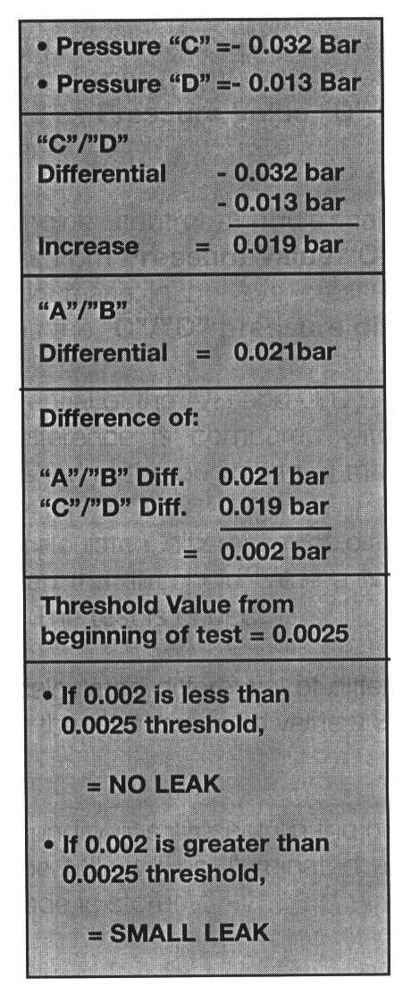
- At 18 seconds the stabilized system pressure is measured and memorized as Pressure Value "C"
- For approximately 9 seconds the captive vacuum is monitored for change (slight vacuum loss). The resulting value is stored as Pressure Value "D" (represented by the 27 sec mark).
- The engine control module calculates the pressure increase from Pressure Value "C" to "D" (loss of vacuum = increase in positive pressure). It memorizes this value as the "C"/"D" pressure differential value.
- A differential of the A/B and C/D differences is calculated. This difference is compared with the threshold value established at the beginning of the test.
- If the calculated differential of differences A/B & C/D is less than the threshold value a NO LEAKS ARE PRESENT. The test is ended.
- If the calculated differential of differences A/B and C/D is greater than the threshold value a SMALL LEAK IS PRESENT.
- If the condition is present on the next evaporative system test, the MIL will be illuminated and the model specific fault code is stored.
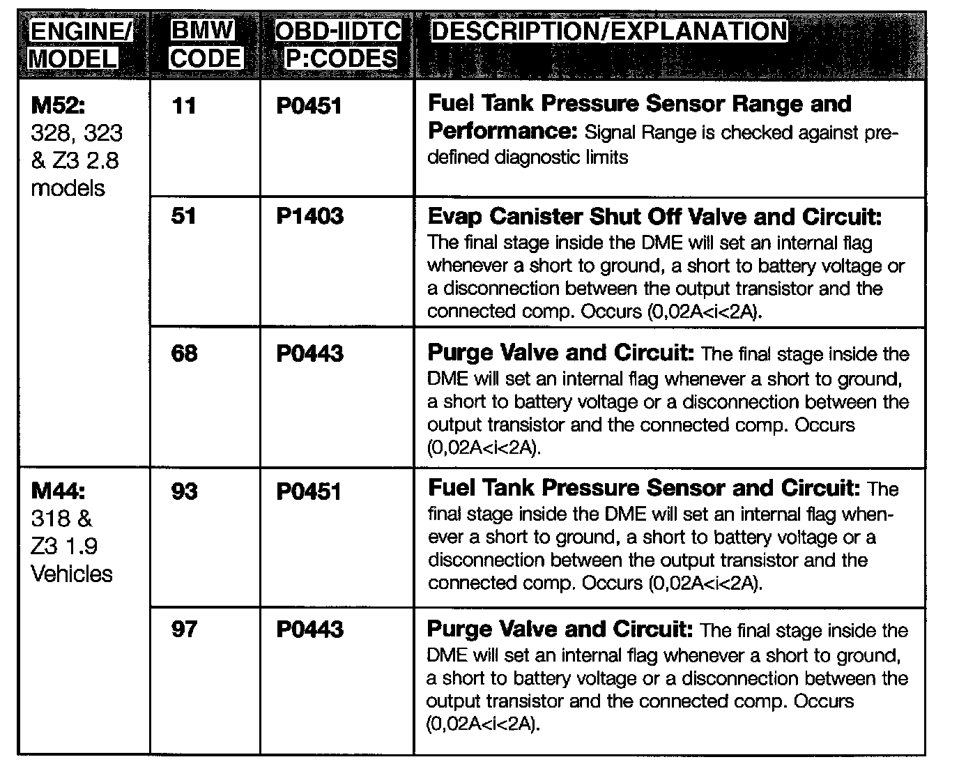
Associated Fault Codes:

Comprehensive Component Testing Fault Codes:
Mechanical conditions that can manifest into logged faults:
Faults with the Evaporative System that can cause faults to manifest in other Engine Control System functions:
Problems with other Engine Control System components/functions that can cause erroneous faults in the Evaporative System Test Function:
Evaporative System Monitoring
(LDP system) - M5.2.1 & MS41.1 ORVR
All criteria are subject to modification and addition for future requirements. Refer to future amendments of section 1968.1 of Title 13, California code of regulations entitled "Malfunction and Diagnostic System Requirements - 1994 and Subsequent Model - Year Passenger Cars, Light Duty Trucks, and Medium Duty vehicles and engines (OBD II)."
Reference: www.arb.ca.gov/msprog/obdprog
Malfunction Criteria:
The system is considered to be malfunctioning when:
- A leak is detected in the system that is equal to or larger than 1.0mm (0.040 in.).
Currently, LDP equipped vehicles are capable of detecting a leak as small as 0.5mm (0.020") though they are not required nor have they been certified to meet this extremely small diameter leak. 0.5mm diameter leak detection will be a requirement for certain LDP vehicles starting with the 1999 model year.
The monitored components include all of the evaporative system components and hoses (except hose from purge valve to intake):

Overview of Evaporative System Leak Monitoring Conditions:
The majority of the Leak Detection tests will occur at cold engine start-up. This time period provides the most accurate results since the vehicle has been stable and fuel temperature is low (conditions are at their best.)
If certain parameters at the time of cold engine start-up occur, the LDP test is "temporarily ended". With this situation, the start of test will occur later in the drive cycle once all system parameters are conclusive.
Before the Evaporative System is tested for leaks, the following conditions must be met:

- Ambient Air Temperature within range: 4.5 to 40° C
- Coolant temp signal within range: 60° C differential from last to current start.
- Altitude < 2400m.
- Intake air temp range: 4.5° C - 125° C.
- Road Speed < 62 MPH.
The LDP is designed to operate within a set temperature range to guarantee accurate leak detection test results. If the ambient temperature value is not within this acceptable range, the test is "temporarily ended".
The engine control module initially determines the ambient temperature value from the instrument cluster via the CAN bus (except on 98 model year 528i). The CAN value is compared against the intake air NTC signal if a specified engine load and or vehicle speed value is exceeded within a certain period of time.
If the intake air temperature sensor signal is lower than the Ambient Air Temp Signal on CAN, the ECM adopts the lower value.
NOTE: The 1998 model year 528i vehicle's CAN bus does not include the instrument cluster. The ambient air temperature signal is monitored directly from the intake air temperature sensor.
Comparing the temperature signals and correcting for the lowest possible temperature value provides safeguards against setting faults and ultimately an erroneous MIL activation. The following scenarios provide insight into how the system can provide guaranteed test results.
- The CAN bus ambient temperature signal is within range and a leak is detected during the leak test. After the conditions are met for comparing the CAN bus signal with the intake air temperature sensor signal which is detected as;
1. out of range: test is ended with no fault stored
2. within range, fault stored
- The ambient temperature is out of range at the time of engine start, this leads to a temporary end of test, the leak test is carried out as soon as all conditions are OK for an accurate test result
- Only when the ambient temperature is within specified range and no leak is detected during the leak test is the system considered to be "leak free"
ECM logic paths for meeting leak detection pre test conditions:
The following flow charts show how the ECM scrutinizes all operating conditions to minimize possible false test results. The Yes/No paths through the flow charts provide four possibilities based on conditions for the system to either abort or run the Leak Detection Test as follows:
Flow Chart 1: Cold Start Conditions.
Yes Path = Continuation into next requirement and ultimately run the LDP while in Cold Start Conditions.
No Path = Go to next flow chart as required:
1. Temporary end of test. Condition causes the ECM to proceed to the "Test Repetition Flow Chart" (checked every 100ms) for repeated attempts.
2. Final end of test. Final end of test informs ECM to proceed to the "Final End Of Test Flow Chart" to determine if the test can continue or abort until next drive cycle. (checked every 100ms).
Flow Chart 1: Cold Start Conditions

Flow Chart 2: Temporary End Of Test

Flow Chart 3: Test Repetition Flow Chart

Flow Chart 4: Final End Of Test Flow Chart

LDP Operation
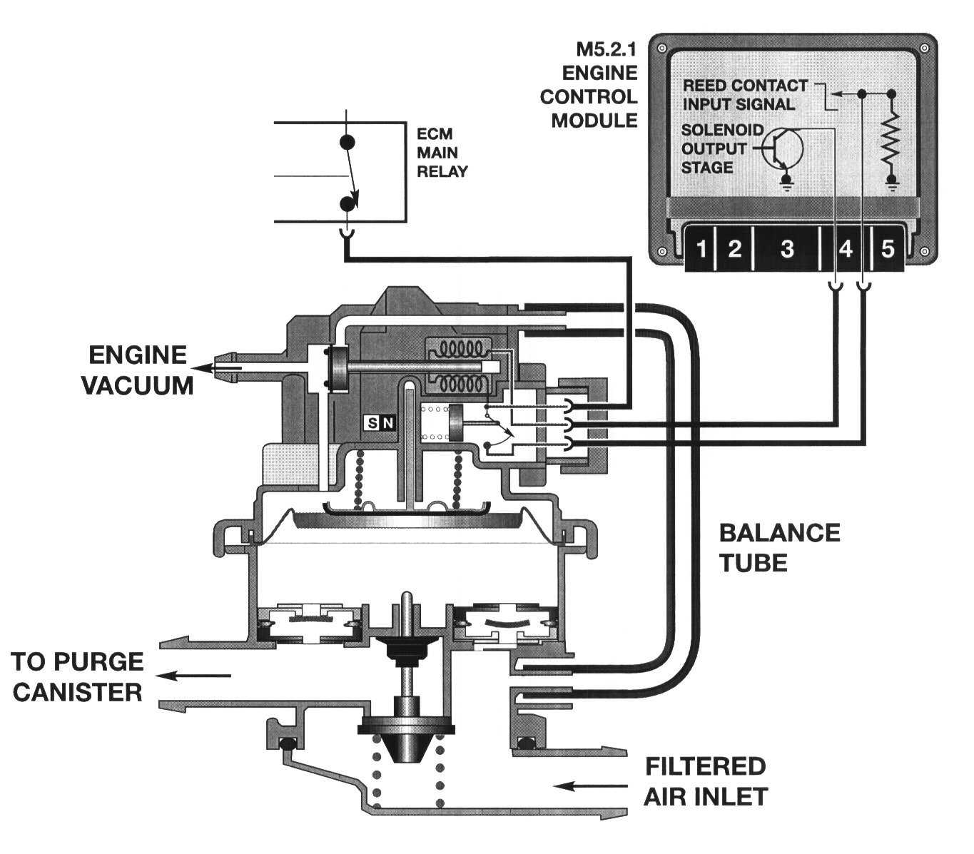


During the start of the evaporative leak detection test, the following occurs:
- The LDP solenoid is energized by the ECM.
- Engine manifold vacuum enters the upper chamber of the LDP to lift up the spring loaded diaphragm pulling ambient air through the filter and into the lower chamber of the LDP through the one way valve.
- The solenoid is then de-energized, spring pressure closes the vacuum port blocking the engine vacuum and simultaneously opens the vent port to the balance tube which releases the captive vacuum in the upper chamber.
- This allows the compressed spring to push the diaphragm down, starting the "limited down stroke". The air that was drawn into the lower chamber of the LDP during the upstroke is forced out of the lower chamber and into the evaporative system.
- This electrically controlled repetitive up/down stroke is cycled repeatedly building up a total pressure of approximately +25mb in the evaporative system. After sufficient pressure has built up (LDP and its cycling is calibrated to the vehicle), the leak diagnosis begins and lasts about 100 seconds.
- The upper chamber contains an integrated reed switch that produces a switched high- low voltage signal that is monitored by the ECM. The switch is opened by the magnetic interruption of the metal rod connected to the diaphragm when in the diaphragm is in the top dead center position.
- The repetitive up/down stroke is confirmation to the ECM that the valve is functioning.
The ECM also monitors the length of time it takes for the reed switch to open, which is opposed by pressure under the diaphragm in the lower chamber. The LDP is still cycled, but at a frequency that depends upon the rate of pressure loss in the lower chamber.
- If the pumping frequency is below parameters, there is no leak present.
- If the pumping frequency is above parameters, this indicates sufficient pressure can not build up in the lower chamber and evaporative system, indicating a leak.
The chart represents the diagnostic leak testing time frame in seconds. When the ignition is switched on, the ECM performs a "static check" of circuit integrity to the LDP pump including the reed switch.
- On cold engine start up, the pump is activated for the first 27 seconds at approximately 166-200 Hz. This rapid pumping phase is required to pressurize the evaporative components.
- Once pressurized, the build up phase then continues from 27-38 seconds.The ECM monitors the system through the reed switch to verify that pressure has stabilized.
- The measuring phase for leak diagnosis lasts from 38-63 seconds. The pump is activated but due to the pressure build up under the diaphragm, the pump moves slower. If the pump moves quickly, this indicates a lack of pressure or a leak. This registers as a fault in the ECM's.
- From 63-100 seconds the pump is deactivated, allowing full down stroke of the diaphragm and rod. At the extreme bottom of rod travel, the canister vent valve is pushed open relieving pressure and allowing normal purge operation when needed.
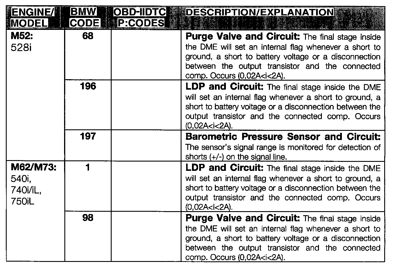
Associated Fault Codes:


Comprehensive Component Testing Fault Codes:
Evaporative Purge Flow Check
(LDP system) - M5.2.1 & MS41.1 ORVR
All criteria are subject to modification and addition for future requirements. Refer to future amendments of section 1968.1 of Title 13, California code of regulations entitled "Malfunction and Diagnostic System Requirements - 1994 and Subsequent Model - Year Passenger Cars, Light Duty Trucks, and Medium Duty vehicles and engines (OBD II).
Reference: www.arb.ca.gov/msprog/obdprog
Malfunction Criteria:

The system is considered to be malfunctioning when:
- No purge air can be detected (Oxygen Sensor Feedback) during regular purge operation.
The purge flow from the charcoal canister through the purge valve is monitored after fuel system adaptation is at closed loop condition. The diagnosis is started during regular purging.
Evaporative Purge Flow Check monitoring structure:
- The system is checked for a rich or lean mixture when the control module starts the test. Flow through the purge valve is assumed as soon as the mixture controller compensates for a rich or lean shift that is greater than a predetermined threshold.
- If an acceptable lean or rich shift is detected, the test is completed, no faults are detected and the evaporative system resumes working normally.
- If the lean/rich shift is detected but not large enough to undoubtedly conclude HC introduction from the evaporative system through the purge valve(s), the engine control module continues to pursue a conclusive test result as follows:
Following conditions must first be met:
1. Finish purge cycle if currently active.
2. Engine at idle speed (LL).
3. Road Speed = 0
4. Engine temp greater than 97° C.
5. Mixture control in closed loop operation.
6. IHKA off (snowflake button not "on")
7. Transmission range Not in "P" or "N".
- With all of the conditions met, the engine control module abruptly cycles the purge valve(s) open and closed several times. The abrupt purge cycling introduces excessive intake air which should noticeably cause the idle speed to fluctuate.
- The control module recognizes the idle fluctuation and determines the purge flow is OK.
- If the test has started and any of the following occur, the test is ended and attempted later in the drive cycle;
1. No change in throttle position
2. Engine idle fluctuation does not go below 560 or above 720 (RPM).
3. Injection fluctuation does not go below 1.3 or above 1.8 (ms).
4. Steering wheel angle does not change more than 5° in either direction (M5.2.1 - from 9-97 production).