Deployment Inside Vehicle
Deploy the inflator modules inside of the vehicle when destroying the vehicle or when salvaging the vehicle for parts. This includes but is not limited to the following situations:- The vehicle has completed its useful life.
- Irreparable damage occurs to the vehicle in a non-deployment type accident.
- Irreparable damage occurs to the vehicle during a theft.
- The vehicle is being salvaged for parts to be used on a vehicle with a different VIN as opposed to rebuilding as the same VIN.
CAUTION: Refer to SIR Inflatable Module Deployment Outside Vehicle Caution in Service Precautions.
1. Turn the ignition switch to the OFF position.
2. Remove the ignition key.
3. Put on safety glasses.
4. Remove all loose objects from the front seats.
5. Disable the SIR system. Refer to SIR Disabling and Enabling Zones.
6. Disconnect the inflatable restraint steering wheel module yellow connector (4) located next to steering column (2).
CAUTION: A deployed dual stage inflator module will look the same whether one or both stages were used. Always assume a deployed dual stage inflator module has an active stage 2. Improper handling or servicing can activate the inflator module and cause personal injury.
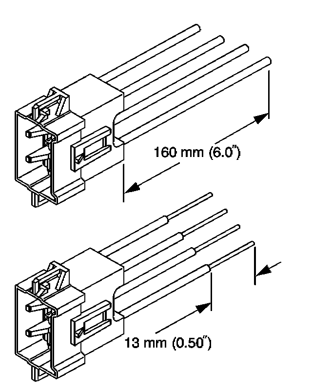
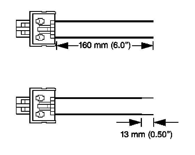
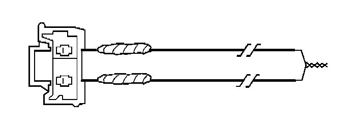
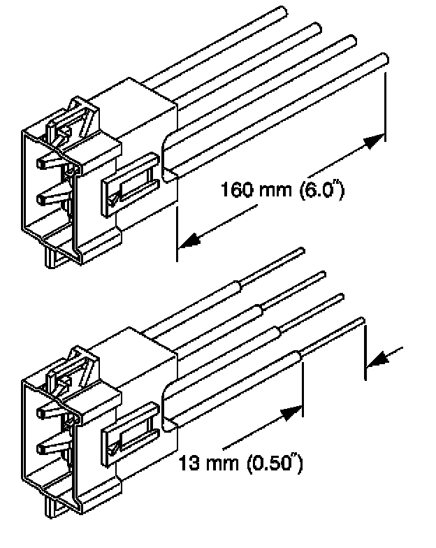
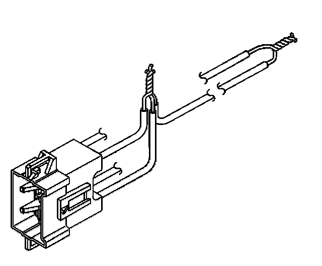
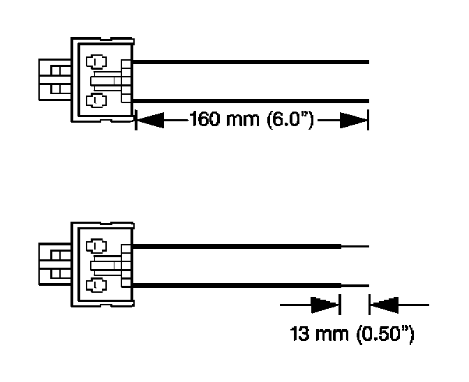
7. Cut the yellow harness connector out of the vehicle, leaving at least 16 cm (6 in) of wire at the connector.
IMPORTANT: If vehicle is equipped with dual stage air bags the steering wheel module and IP module will each have 4 wires and standard air bags will only have 2 wires. Refer to SIR Connector End Views for determining high and low circuits.
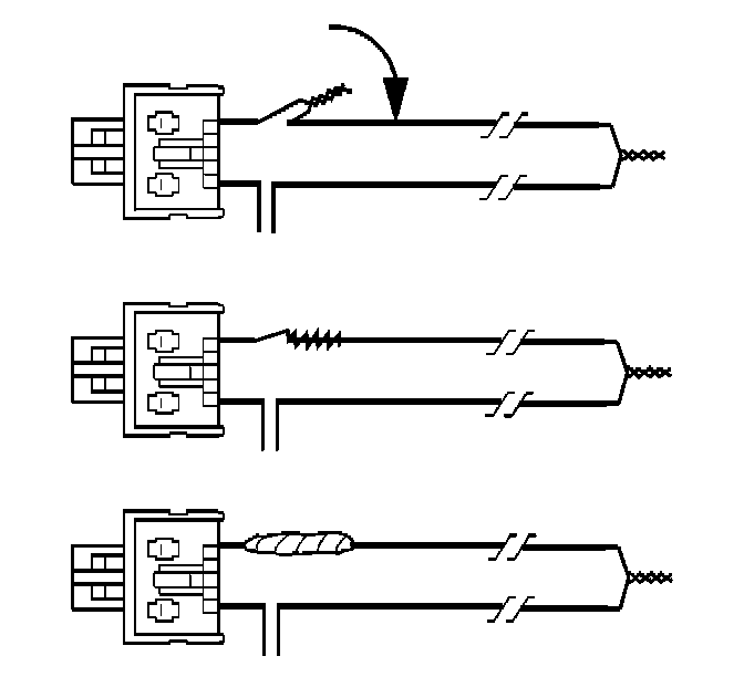
8. Strip 13 mm (0.5 in) of insulation from each of the connector wire leads.
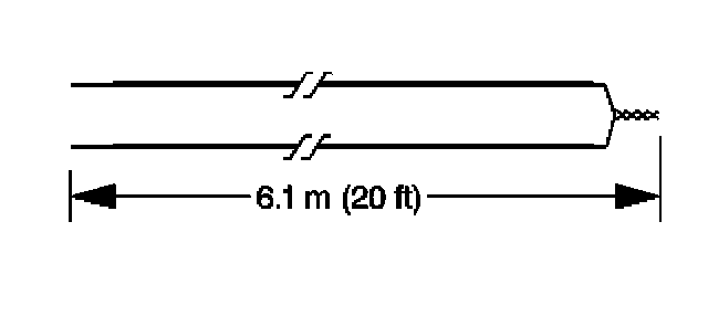
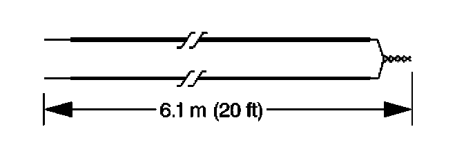
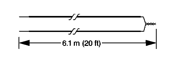
9. Cut 2 6.1 m (20 ft) deployment wires from a 0.8 mm (18 gage) or thicker multi-strand wire. Use these wires to fabricate the driver deployment harness.
10. Strip 13 mm (0.5 in) of insulation from both ends of the wires cut in the previous step.
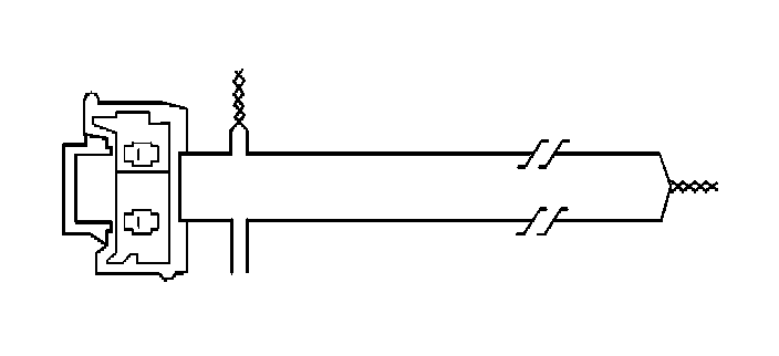
11. Twist together one end from each of the wires in order to short the wires. Deployment wires shall remain shorted, and not connected to a power source until you are ready to deploy the inflator module.
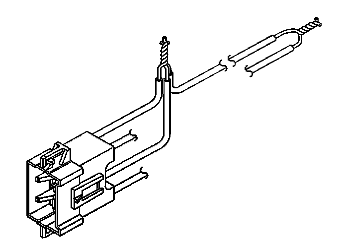
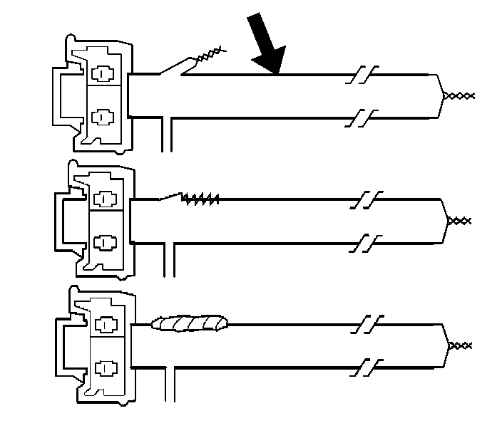
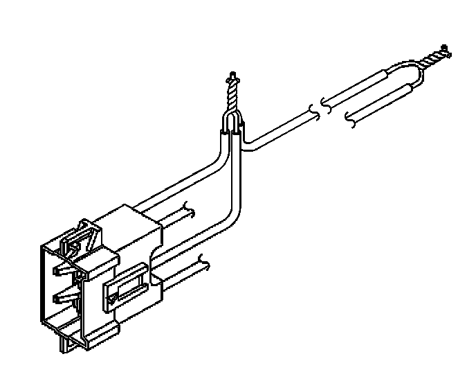
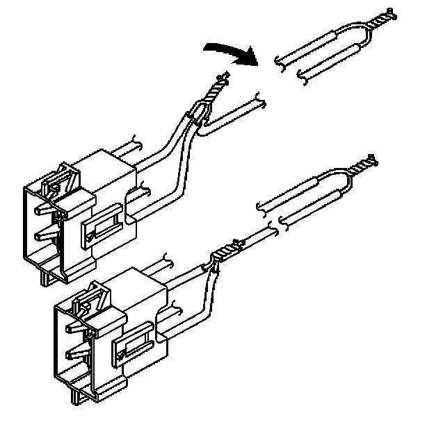
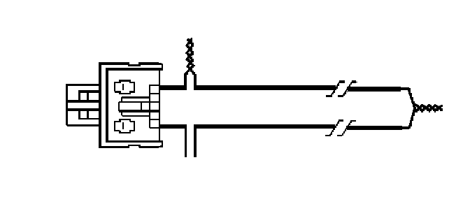
12. Twist together the two connector wire leads of the high circuits from both stages of the IP module to one of the deployment harness wires. Refer to SIR Connector End Views in order to determine the correct circuits.
13. Inspect that the 3 wire connection is secure.
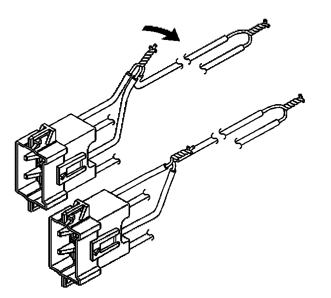
14. Bend flat the twisted connection.
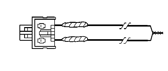
15. Secure and insulate the 3 wire connection to deployment harness using electrical tape.
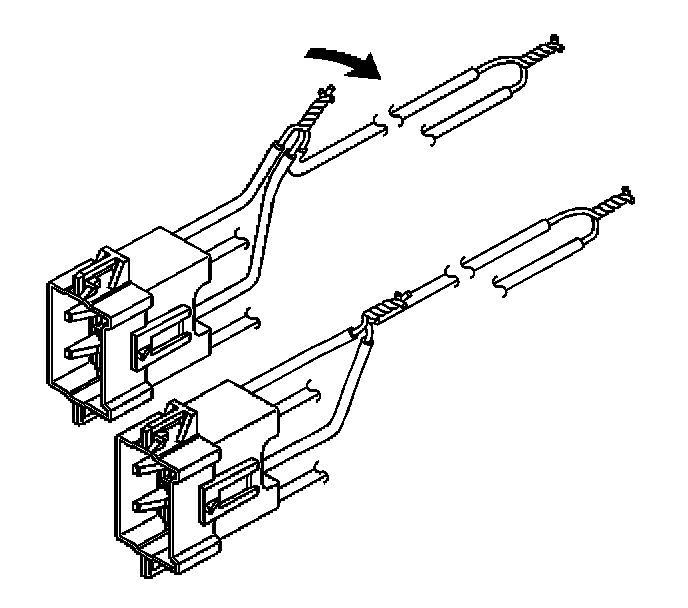
16. Twist together 2 connector wire leads of the low circuits from both stages of the steering wheel module to one sets of deployment wires. Refer to SIR Connector End Views in order to determine the correct circuits.
17. Inspect that the 3 wire connection is secure.
18. Bend flat the twisted connection.
19. Secure and insulate the 3 wire connection to deployment harness using electrical tape.
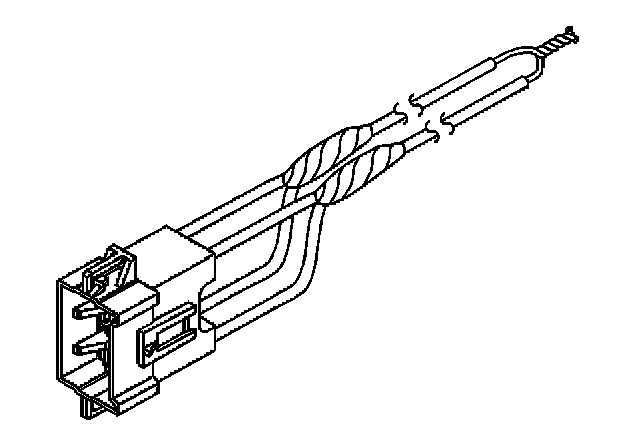
20. Connect the deployment harness to the steering wheel module in-line connector.
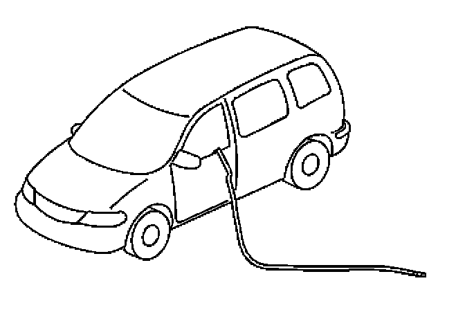
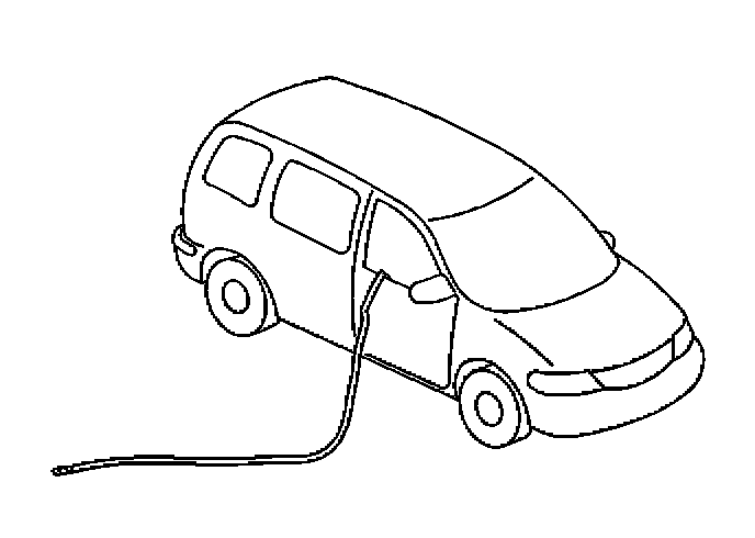
21. Route the deployment harness out of the driver side of the vehicle.
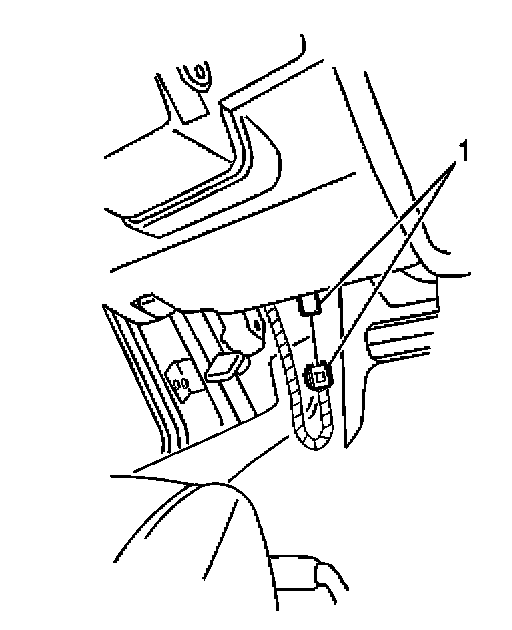
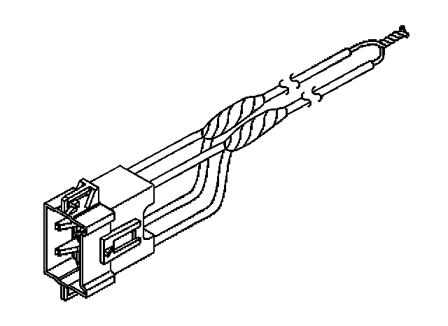
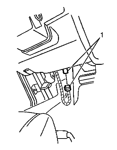
22. Disconnect the driver side impact module yellow connector (1) from the vehicle wiring harness (4) located under the driver seat.
23. Cut the 2 side impact module wires leading to the yellow harness connector, leaving at least 16 cm (6 in) of wire at the connector.
24. Strip 13 mm (0.5 in) of insulation from each of the side impact module connector wire leads.
25. Cut 2 6.1 m (20 ft) deployment wires from a 0.8 mm (18 gage) or thicker multi-strand wire. Use these wires to fabricate the deployment harness.
26. Strip 13 mm (0.5 in) of insulation from both ends of the wires cut in the previous step.
27. Twist together 1 end from each of the wires in order to short the wires. Deployment wires shall remain shorted, and not connected to a power source until you are ready to deploy the side impact module.
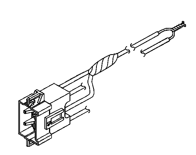
28. Twist together 1 connector wire lead to one deployment wire.
29. Inspect that the previous connection is secure.
30. Bend flat the twisted connection.
31. Secure and insulate the connection using electrical tape.
32. Twist together, bend, and tape the remaining connector wire lead to the remaining deployment wire.
33. Connect the deployment harness to the side impact module - LF.
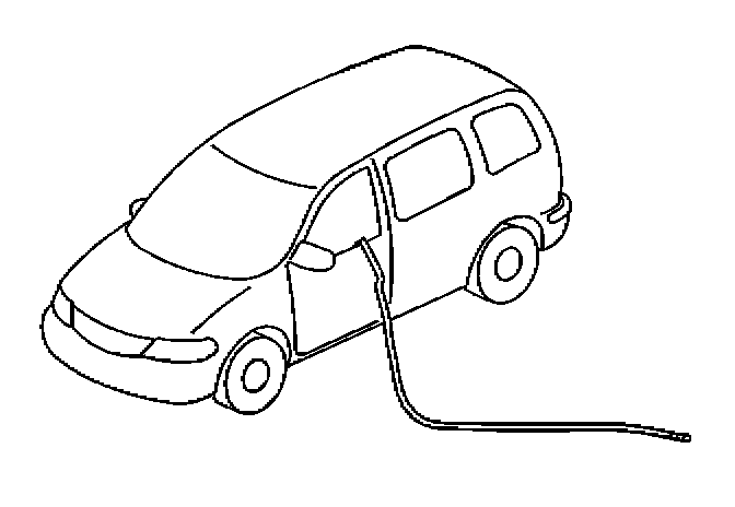
34. Route the deployment harness out of the driver side of the vehicle.
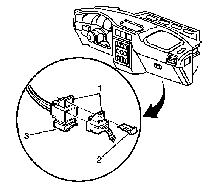
35. Disconnect the IP module yellow harness connector (2) above passenger side sound insulator.
36. Cut the yellow harness connector out of the vehicle, leaving at least 16 cm (6 in) of wire at the connector.
IMPORTANT: If vehicle is equipped with dual stage air bags the IP module will each have 4 wires and standard air bags will only have 2 wires. Refer to SIR Connector End Views for determining high and low circuits.
37. Strip 13 mm (0.5 in) of insulation from each of the connector wire leads.
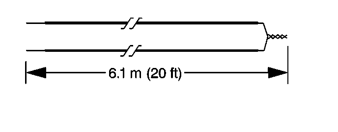
38. Cut two 6.1 m (20 ft) deployment wires from a 0.8 mm (18 gage) or thicker multi-strand wire. These wires will be used to fabricate the passenger deployment harness.
39. Strip 13 mm (0.5 in) of insulation from both ends of the wires cut in the previous step.
40. Twist together one end from each of the wires in order to short the wires.
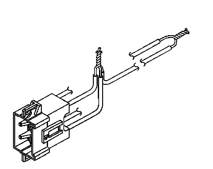
41. Twist together the two connector wire leads of the high circuits from both stages of the IP module to one of the deployment harness wires. Refer to SIR Connector End Views in order to determine the correct circuits.
42. Inspect that the 3 wire connection is secure.
43. Bend flat the twisted connection.
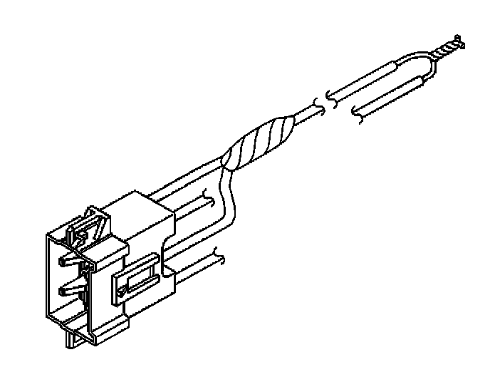
44. Secure and insulate the 3 wire connection to deployment harness using electrical tape.
45. Twist together the two connector wire leads of the low circuits from both stages of the IP module to the deployment harness wire. Refer to SIR Connector End Views in order to determine the correct circuits.
46. Inspect that the 3 wire connection is secure.
47. Bend flat the twisted connection.
48. Secure and insulate the 3 wire connection to deployment harness using electrical tape.
49. Connect the deployment harness to the IP module in-line connector.
50. Route the deployment harness out of the passenger side of the vehicle.
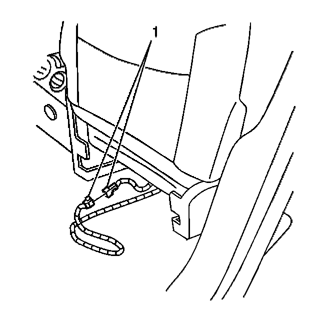
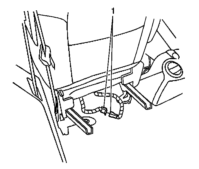
51. Disconnect the passenger side impact module yellow connector (1) from the vehicle wiring harness (4) located under the passenger seat.
52. Cut the two side impact module wires leading to the yellow harness connector, leaving at least 16 cm (6 in) of wire at the connector.
53. Strip 13 mm (0.5 in) of insulation from each of the side impact module connector wire leads.
54. Cut two 6.1 m (20 ft) deployment wires from a 0.8 mm (18 gage) or thicker multi-strand wire. Use these wires to fabricate the deployment harness.
55. Strip 13 mm (0.5 in) of insulation from both ends of the wires cut in the previous step.
56. Twist together one end from each of the wires in order to short the wires. Deployment wires shall remain shorted, and not connected to a power source until you are ready to deploy the side air bag module.
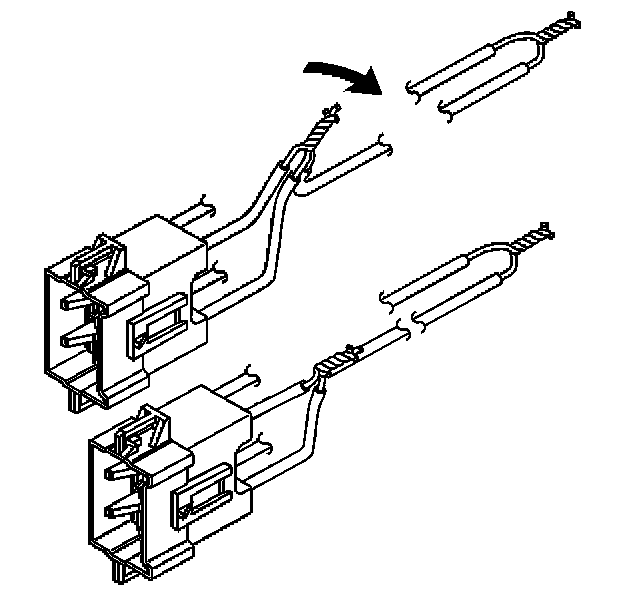
57. Twist together one connector wire lead to one deployment wire.
58. Inspect that the previous connection is secure.
59. Bend flat the twisted connection.
60. Secure and insulate the connection using electrical tape.
61. Twist together, bend, and tape the remaining connector wire lead to the remaining deployment wire.
62. Connect the deployment harness to the side impact module - RF.
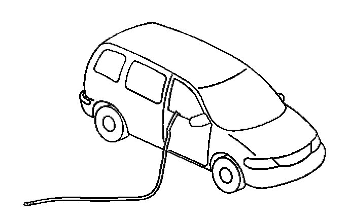
63. Route the deployment harness out of the passenger side of the vehicle.
64. Completely cover the windshield and front door window openings with a drop cloth.
65. Stretch out all of the deployment harness wires on the left and right side of the vehicle to their full length.
66. Deploy each deployment loop one at a time.
67. Place a power source, 12 V minimum/2 A minimum, i.e., a vehicle battery, near the shorted end of the harnesses.
68. Separate the one set of wires and touch the wires ends to the power source in order to deploy the inflator modules, doing one module at a time.
69. Disconnect the deployment harness from the power source and twist the wire ends together.
70. Continue the same process with the remaining deployment harnesses that are available.
71. Remove the drop cloth from the vehicle.
72. Disconnect all harnesses from the vehicle.
73. Discard the harnesses.
74. Scrap the vehicle in the same manner as a non-SIR equipped vehicle.
75. If one or all of the inflator modules did not deploy, perform the following steps to remove the undeployed module(s) from the vehicle:
- If the steering wheel module did not deploy, refer to Inflatable Restraint Steering Wheel Module Replacement (Aztek)Inflatable Restraint Steering Wheel Module Replacement (Rendezvous).
- If the IP module did not deploy, refer to Inflatable Restraint Instrument Panel Module Replacement (Rendezvous)Inflatable Restraint Instrument Panel Module Replacement (Aztek).
- If the side impact module - LF did not deploy, refer to Inflatable Restraint Side Impact Module Replacement - LH.
- If the side impact module - RF did not deploy, refer to Inflatable Restraint Side Impact Module Replacement - RH.
76. Call Technical Assistance Group.