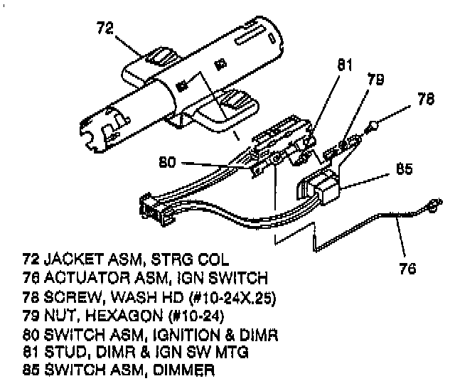
Dimmer Switch - Column Shift


REMOVE OR DISCONNECT
1. Disable the Supplemental Inflatable Restraint (SIR) system; refer to "Disabling the SIR System".
2. Negative (-) battery cable.
3. Washer head screw (78).
4. Hexagon nut (79).
^ Ground wire with ring terminal from stud (81).
5. Dimmer switch assembly (85) from dimmer switch rod (77).
6. Wire harness strap (82).
7. Positive assurance terminal connector from bulkhead connector.

8. Dimmer switch wires from positions 4B, 5B, and 5C of bulkhead connector.
^ Insert small blade screwdriver at rear of connector, push up locking tang on wire connection and remove wire.
INSTALL OR CONNECT
CAUTION: Always use the correct fastener in the correct location. When you replace a fastener, use ONLY the exact part number for that application. The Manufacturer will call out those fasteners that require a replacement after removal. The Manufacturer will also call out the fasteners that require thread lockers or thread sealant. UNLESS OTHERWISE SPECIFIED, do not use supplemental coatings (paints, greases, or other corrosion inhibitors) on threaded fasteners or fastener joint interfaces. Generally, such coatings adversely affect the fastener torque and the joint clamping force, and may damage the fastener. When you install fasteners, use the correct tightening sequence and specifications. Following these instructions can help you avoid damage to parts and systems.
CAUTION: Ensure all fasteners are securely seated before applying required torque. Failure to do so may result in component damage or malfunctioning of steering column.
1. Dimmer switch wires to bulkhead connector.
^ Tan - 4B.
^ Green - 5B.
^ Yellow - 5C.
^ Seat wire connections into bulkhead connector until securely locked in.
2. Positive assurance terminal connector to bulkhead connector.
3. Wire harness strap (82).
4. Dimmer switch assembly (85).
^ Ground wire with ring terminal from turn signal switch wire harness to stud (81).
5. Hexagon nut (79) and washer head screw (78).
^ Tighten finger tight.
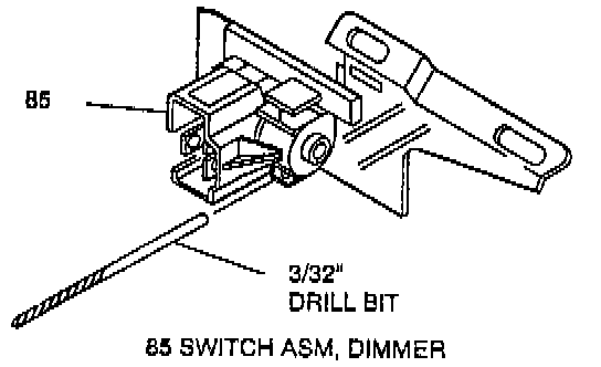
^ Adjust the dimmer switch (85).
a. Place 3/32-inch drill bit in hole on switch to limit travel.
b. Position switch on column and push against dimmer switch rod (77) to remove all lash.
c. Remove drill bit.
^ Tighten screw (78) and nut (79) to 4.0 Nm (35 lb in).
6. Negative (-) battery cable.
7. If all service operations are completed, enable the SIR system; refer to "Enabling the SIR System".