Power Mode Description and Operation
Power Mode Description and Operation
Power to many of this vehicle's circuits are controlled by the module that is designated the power mode master (PMM). This vehicle PMM is the body control module (BCM). The PMM controls which power mode (Run, Accessory, Crank, Retained Accessory Power, or Off) is active.
Serial Data Power Mode
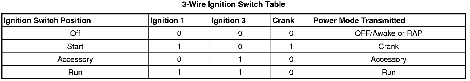
On vehicles that have several control modules connected by serial data circuits, one module is the power mode master (PMM). On this vehicle, the PMM is the body control module (BCM). The PMM receives 3 discrete ignition switch signals to differentiate which power mode will be sent over the Serial Data circuits. The table below illustrates the state of these inputs in correspondence to the ignition switch position:
Relay Controlled Power Mode
The body control module (BCM) uses the discrete ignition switch inputs ignition 1, ignition 3 and crank to distinguish the correct power mode. Once the BCM has determined the power mode selected by the vehicle operator it will energize the Ignition relay, Run relay and retained accessory power (RAP) relay, depending on which power mode is selected.
Ignition 1 Relay
The relay uses a Hot At All Times B+ power source derived from the underhood electrical center. The ignition 1 relay supplies a power signal to the following circuits when the Run or Crank power mode is selected:
* AC clutch relay
* ABS STG angle sensor
* Antilock brake system (ABS) yaw sensor
* Auxiliary power drop connector
* Crank relay
* Cruse control switch
* Electronic brake control module (EBCM)
* Engine control module (ECM)
* Heating, ventilation, and air conditioning module (HVAC)
* Ignition control module (ICM)
* Instrument panel cluster (IPC)
* Sensing and diagnostic module (SDM)
* Transmission solenoid circuit
Retained Accessory Power (RAP) Relay
The RAP relay is energized when the Run or Accessory power mode has been selected. The relay uses a Hot At All Times B+ power source derived from the underhood electrical center. The B+ power source is protected by the 50 Amp BATT MAIN 2 fuse. The BCM also energizes the relay for 10 minutes after the vehicle operator transitions the ignition switch from Accessory to OFF or Run to OFF positions. The following circuits are controlled by the RAP relay:
* Power sunroof
* Power windows
Fail-Safe Operation
Since the operation of the vehicle systems depends on the power mode, there is a fail-safe plan in place should the power mode master (PMM) fail to send a power mode message. The fail-safe plan covers those modules using exclusively serial data control of power mode as well as those modules with discrete ignition signal inputs.
Serial Data Messages
The modules that depend exclusively on serial data messages for power modes stay in the state dictated by the last valid PMM message until they can check for the engine run flag status on the serial data circuits. If the PMM fails, the modules monitor the serial data circuit for the engine run flag serial data. If the engine run flag serial data is True, indicating that the engine is running, the modules fail-safe to RUN. In this state the modules and their subsystems can support all operator requirements. If the engine run flag serial data is False, indicating that the engine is not running, the modules fail-safe to OFF-AWAKE. In this state the modules are constantly checking for a change status message on the serial data circuits and can respond to both local inputs and serial data inputs from other modules on the vehicle.
Discrete Ignition Signals
Those modules that have discrete ignition signal inputs also remain in the state dictated by the last valid PMM message received on the serial data circuits. They then check the state of their discrete ignition input to determine the current valid state. If the discrete ignition input is active, battery positive voltage, the modules will fail-safe to the RUN power mode. If the discrete ignition input is not active, open or 0 volts, the modules will fail-safe to OFF-AWAKE. In this state the modules are constantly checking for a change status message on the serial data circuits and can respond to both local inputs and serial data inputs from other modules on the vehicle.
BCM Wake-Up/Sleep States
The body control module (BCM) is able to control or perform all of the BCM functions in the wake-up state. The BCM enters the sleep state when active control or monitoring of system functions has stopped, and the BCM has become idle again. The BCM must detect certain wake-up inputs before entering the wake-up state. The BCM monitors for these inputs during the sleep state, where the BCM is able to detect switch transitions that cause the BCM to wake-up when activated or deactivated. Multiple switch inputs are needed in order to sense both the insertion of the ignition key and the power mode requested. This would allow the BCM to enter a sleep state when the key is IN or OUT of the ignition.
The BCM will enter a wake-up state if any of the following wake-up inputs are detected:
* Activity on the serial data line
* Detection of a battery disconnect and reconnect condition
* Headlamps are ON.
* Ignition is turned ON.
* Key-in-ignition switch
* Park lamps are ON.
The BCM will enter a sleep state when all of the following conditions exist:
* The ignition switch is OFF.
* No activity exists on the serial data line.
* No outputs are commanded.
* No delay timers are actively counting.
* No wake-up inputs are present.
If all these conditions are met the BCM will enter a low power or sleep condition. This condition indicates that the BCM, which is the power mode master (PMM) of the vehicle, has sent an OFF-ASLEEP message to the other systems on the serial data line.