Interlock Solenoid Assembly - With Column Shift
INTERLOCK SOLENOID ASSEMBLY
Remove or Disconnect

1. Disable the SIR system.
2. Negative (-) battery cable.
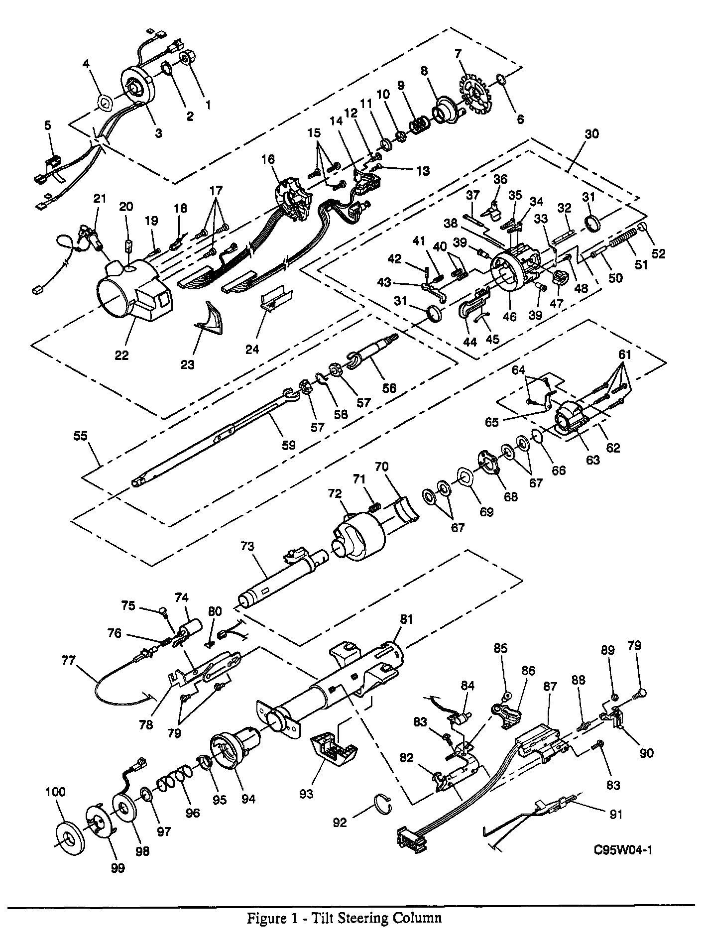
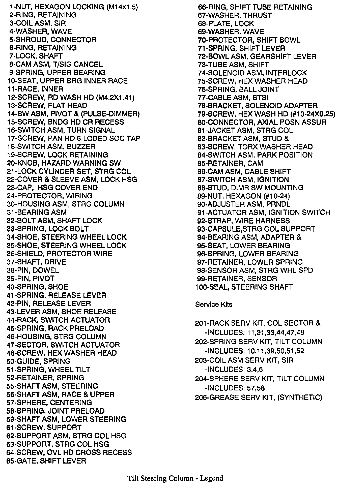
3. Axial position assurance Connector (80) and vehicle wire harness connector from interlock solenoid assembly (74).
Important: Brake Transmission Shift Interlock (BTSI) cable assembly (77) must remain straight and must not be kinked during removing and installing.
4. BTSI cable assembly (77) from interlock solenoid assembly (74).
A. Cable mounting clip from solenoid adapter bracket (78).
B. Ball joint socket from solenoid (74).
C. Ball joint spring (76).
5. Hexagon washer head screw (75).
- Interlock solenoid assembly (74).
Install or Connect

NOTICE: When fasteners are removed, always reinstall them at the same location from which they were removed. If a fastener needs to be replaced, use the correct part number fastener for that application. Ifthe correct part number fastener is not available, a fastener of equal size and strength (or stronger) may be used. Fasteners that are not reused, and those requiring thread locking compound will be called out. The correct torque value must be used when installing fasteners that require it. If the above conditions are not followed, parts or system damage could result.
NOTICE: Ensure all fasteners are securely seated before applying required torque. Failure to do so may result in component damage or malfunctioning of steering column.
1. Interlock solenoid assembly (74) to solenoid adapter bracket (78).
2. Hexagon washer head screw (75).
Tighten
Screw (75) to 4.0 Nm (35 lb.in.).
3. Unlock BTSI cable assembly (77).
- Disengage locking button to allow cable movement during adjustment.
4. BTSI cable assembly (77) to solenoid adapter bracket (78) with locking button disengaged.
5. Ball joint spring (76) and ball joint socket to solenoid (74).
Adjust
- Interlock solenoid assembly (74).
A. Lock cylinder set to "RUN" position.
B. Shift column out "PARK" position.
C. The locking button must be disengaged to allow cable movement. Pull cable (77) away from solenoid (74) until cable fitting starts to extend, compressing spring inside joint socket. (Do not extend cable fitting.)
- Let cable move back 1.0 to 2.0 mm.
- Engage locking button.
6. Vehicle wire harness connector to interlock solenoid assembly (74).
7. Negative (-) battery cable.
IMPORTANT: During Inspection and Adjustment of interlock solenoid assembly (74), solenoid will become hot.
Inspect
- Function check interlock solenoid assembly (74) for proper operation.
- Solenoid (74) must lock gearshift lever bowl assembly (72) whenever steering column is in "PARK" and when trying to shift from "PARK" without pressing brake pedal (solenoid is energized).
- Solenoid (74) must release gearshift lever bowl assembly (72) when pressure is applied to brake pedal. (solenoid is de-energized).
- Readjust if needed.
8. If all service operations are completed, enable the SIR system.