Transmission Diagnostics
Diagnostic Chart:

Diagnostic Chart (cont'd):

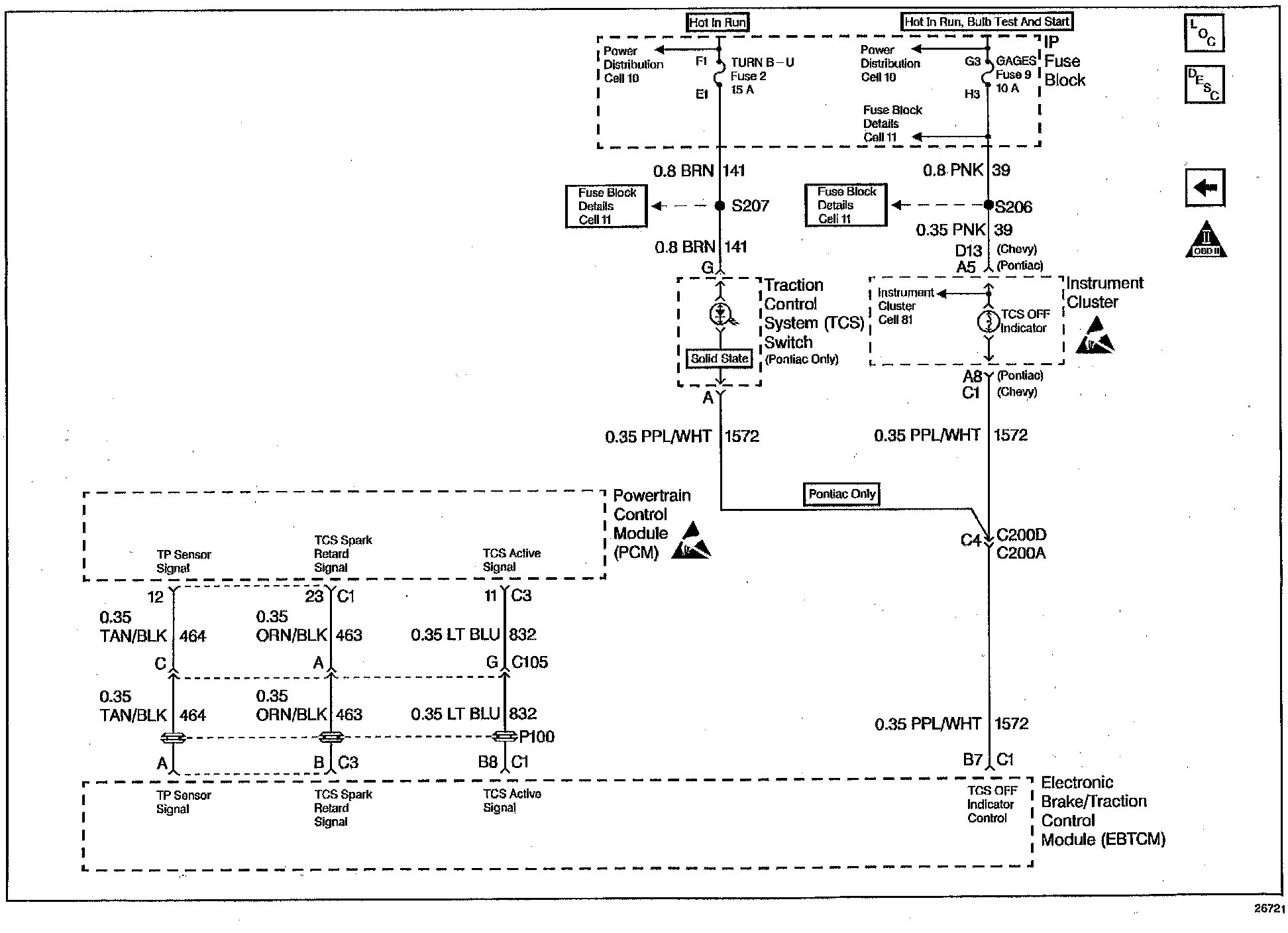
Wiring Diagram:
CIRCUIT DESCRIPTION
The PCM receives an input signal from the traction control system (TCS) indicating that a traction control event is occuring. The Battery Positive signal during normal operation becomes zero volts during the traction control event. The PCM inhibits upshifts, downshifts, and TCC operation during a traction control event.
When the PCM detects an active traction control circuit in Park and Neutral, then DTC P1572 sets. DTC P1572 is a type A DTC.
CONDITIONS FOR SETTING THE DTC
- No TFP Val Position Sw DTC P1810
- The transmission is in Park or Neutral.
- The traction control is active
- All conditions are satisfied for 6.4 seconds.
ACTION TAKEN WHEN THE DTC SETS
- If the TCS is active, then the TCC is OFF.
- The PCM inhibits 4th gear if in hot mode.
- The PCM freezes shift adapts.
- The PCM illuminates the Malfunction Indicator Lamp (MIL).
CONDITIONS FOR CLEARING THE MIL/DTC
- The PCM turns OFF the MIL after three consecutive ignition cycles without a failure reported.
- A scan tool can clear the DTC from the PCM history. The PCM clears the DTC from the PCM history if the vehicle completes 40 warm-up cycles without a failure reported.
- The PCM cancels the DTC default actions when the fault no longer exists and the ignition is OFF long enough in order to power down the PCM.
DIAGNOSTIC AIDS
- Inspect the wiring for any poor electrical connections at the PCM. Inspect the wiring at the TCC brake switch. Look for the following conditions:
- A bent terminal
- A backed out terminal
- A damaged terminal
- Poor terminal tension
- A chafed wire
- A broken wire inside the insulation
- When diagnosing for an intermittent short or an open condition, massage the wiring harness while watching the test equipment for a change.
TEST DESCRIPTION
The item numbers below refer to the Step numbers on the diagnostic chart.
3. Disconnecting the C3 PCM connector isolates the PCM from the traction control system.