P1626


Circuit Description
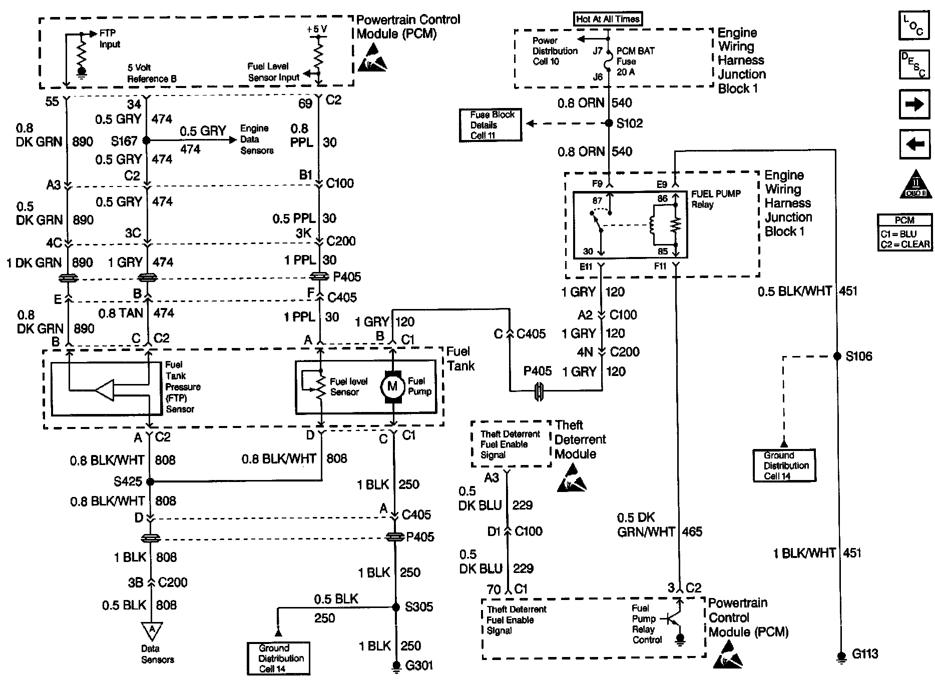
The Vehicle Theft Deterrent module produces the Theft Deterrent Fuel Enable signal when the ignition is ON and the proper key resistor pellet is sensed by the Vehicle Theft Deterrent module. The PCM monitors the Fuel Enable signal during crank. If the proper signal is present on the Theft Deterrent Fuel Enable circuit, the PCM enables fuel delivery to allow the engine to start. If the PCM detects that the fuel enable signal is not present or incorrect while the engine is running, DTC P1626 will be set. The engine will continue to start and run as long as DTC P1626 is stored and the malfunction condition affects only the Theft Deterrent Fuel enable circuit. If the problem affects inputs to the Vehicle Theft Deterrent module, the starter motor may be disabled.
Conditions for Running the DTC
The engine is running.
Conditions for Setting the DTC
^ The PCM detects an incorrect signal on the Theft Deterrent Fuel Enable Circuit.
^ The above conditions are present for longer than 2 seconds.
Action Taken When the DTC Sets
^ The PCM will not illuminate the Malfunction Indicator Lamp (MIL).
^ The PCM will store conditions which were present when the DTC set as Fail Records data only. This information will not be stored as Freeze Frame data.
Conditions for Clearing the MIL/DTC
^ A history DTC will clear after 40 consecutive warm-up cycles have occurred without a malfunction.
^ DTC can be cleared by using a scan tool.
Diagnostic Aids
An intermittent may be caused by a poor connection, rubbed through wire insulation or a wire broken inside the insulation. Check for the following conditions:
^ Poor connection.
Inspect the PCM and Vehicle Theft Deterrent (VTD) module harness and connectors for improper mating, broken locks, improperly formed or damaged terminals, and poor terminal to wire connection.
^ Damaged harness.
Inspect the wiring harness for damage. If the harness appears to be OK, disconnect the VTD module, turn the ignition ON and observe a digital multimeter connected to the theft deterrent fuel enable circuit at the VTD module harness connector while moving connectors and wiring harnesses related to the vehicle theft deterrent system. A change in voltage will indicate the location of the malfunction.
Reviewing the Fail Records vehicle mileage since the diagnostic test last failed may help determine how often the condition that caused the DTC to be set occurs. This may assist in diagnosing the condition.
Test Description
Number(s) below refer to the step number(s) on the Diagnostic Table.
9. This vehicle is equipped with a PCM which utilizes an Electrically Erasable Programmable Read Only Memory (EEPROM). When the PCM is being replaced, the new PCM must be programmed.