Internal Components
INTERNAL COMPONENTSNP233 Transfer Case Components:
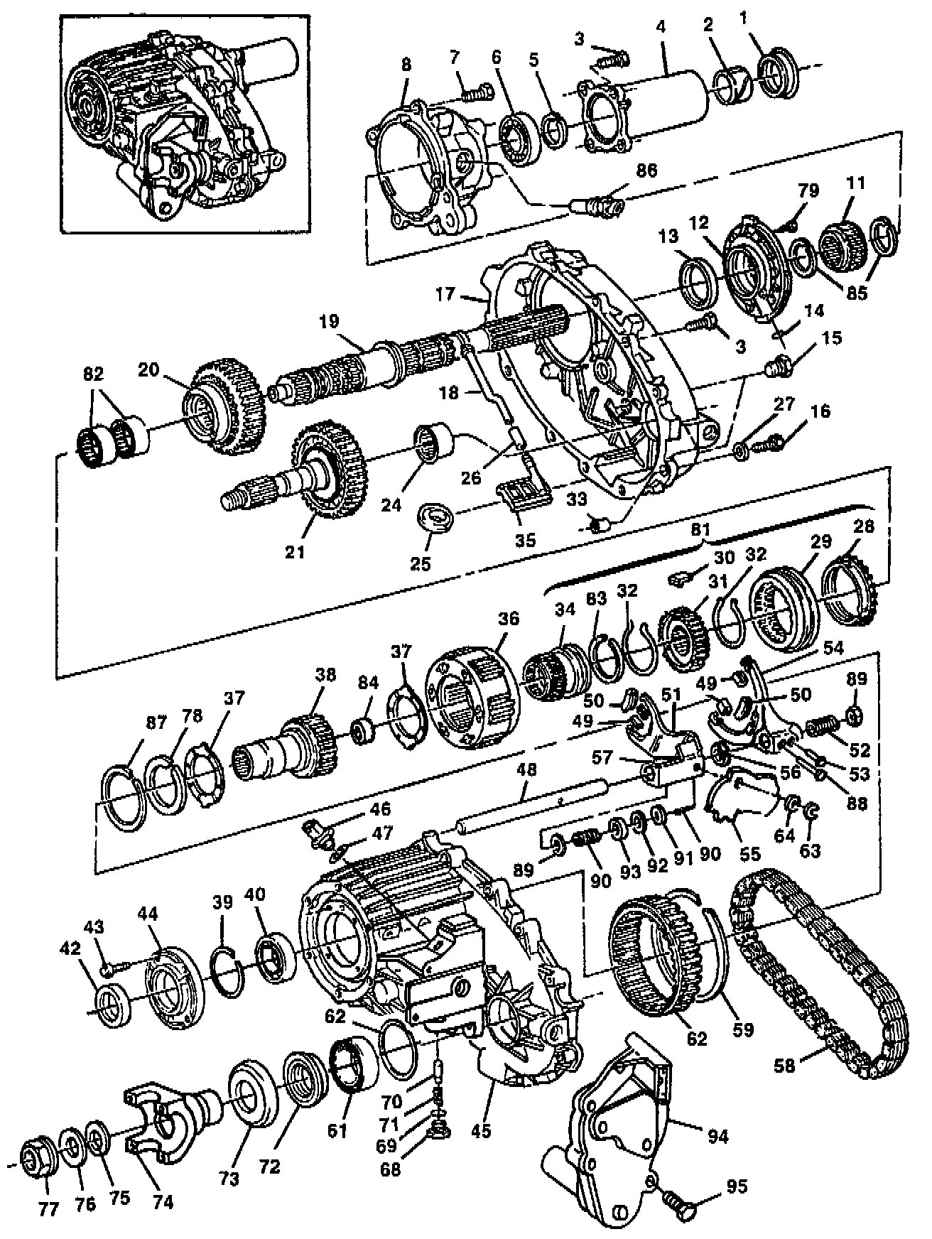
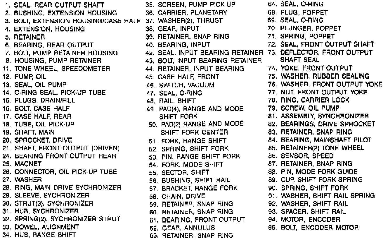
NP233 Transfer Case Components - Legend:
TOOLS REQUIRED
- J 8092 Driver Handle
- J 36370 Bearing Installer/Remover
- J 29170 Bearing Remover
- J 29369-1 Bearing Remover
- J 9276-21 Adapter
- J 2619-01 Slide Hammer
- J 33790 Bearing Remover
REMOVE OR DISCONNECT
IMPORTANT
- The annulus gear found in this transfer case is not serviceable or removable, and should only be replaced as a unit with the front case half. If the annulus gear is removed, damage will result to the case.
Fig. 43 Oil Pump, Pickup Tube & Screen Removal:
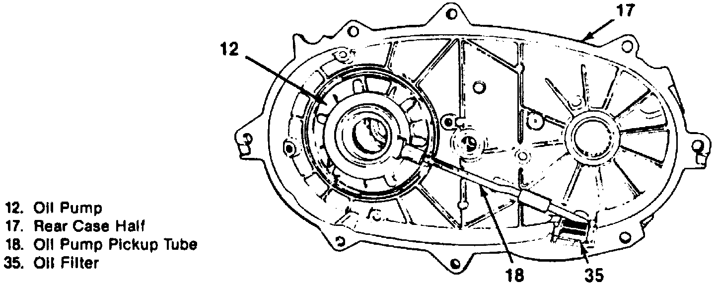
1. Oil pump (12), pickup tube (18), O-ring (14), and pump pickup filter (35) from the rear case half.
2. Fork shift spring.
3. Mainshaft (19), chain (58), and driven sprocket (22) from the front case half (45) as a unit. Mode shift fork (54) and shift rail (48) will be removed with the mainshaft.
4. Retainer (snap ring) (83) from the mainshaft (19).
5. Synchronizer assembly (81).
6. Drive sprocket (20) from the mainshaft (19).
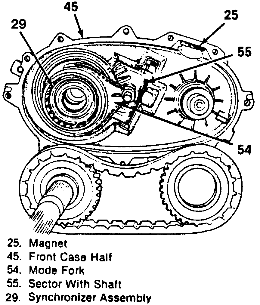
7. Range shift fork assembly (51) and range shift hub (34) from the planetary carrier (36). It is necessary to rotate the sector shaft (55) to obtain clearance when removing the range fork (51) (figure 3).
8. Retainer (snap ring) (63), O-ring (64), and shift sector (55) from the front case half (45).
9. Input bearing retainer bolts (43) and input bearing retainer (44) from the front case half (45).
10. Bearing retainer (snap ring) (39).
11. Planetary carrier (36) and the input gear (38) from the annulus gear (62) using a soft faced hammer.
12. Input bearing (40) from the front case half (45) using J 36370 and J 8092.
13. Drive sprocket bearings (82) from the drive sprocket (20) using J 29170 and J 8092.
Fig. 46 Input Gear Bearing Removal:
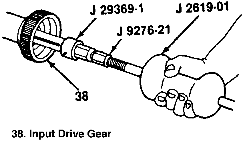
14. Needle bearings (84) from the input gear (38) using J 29369-1, J 9276-21, and J 2619-01.
15. Front output shaft seal (72) from the front case half (45).
16. Front output bearing retainer ring (snap ring) (60).
17. Front output bearing (61) from the front case half (45) using J 33790 and J 8092.
18. Seal (1) from the mainshaft extension housing (4).
19. Seal (42) from the input bearing retainer (44).
Front Output Shaft Rear Bearing Removal:
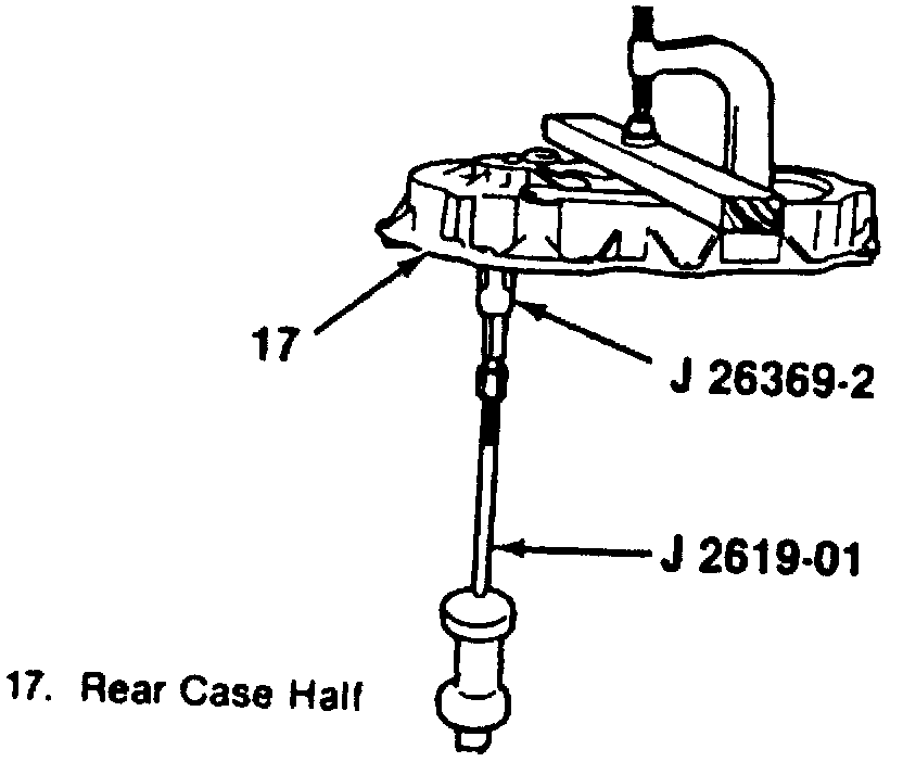
20. Front output rear bearing (24) from the rear case half (17) using J 2619-01 and J 29369-2.
21. Mainshaft bearing (6) from the oil pump retainer (8) using J 33790.
22. Magnet (25) from the front case half (45).
DISASSEMBLE
- Mark the location of the synchronizer hub and sleeve to aid in assembly. Synchronizer teeth must align with struts (30).
1. Main drive synchronizer stop ring (28) from the synchronizer sleeve (29).
2. Spring retainers (32) from the synchronizer hub (31).
3. Synchronizer hub (31) from the synchronizer (29).
4. Oil pump screws (79) from the oil pump (12).
IMPORTANT
- The oil pump is not a serviceable unit and should be replaced if it is defective.