Keyless Transmitter Button, Rear Door - Inoperative
File In Section: 8 - Chassis/Body ElectricalBulletin No.: 46-81-13
Date: February, 1995
Subject:
Rear Door Keyless Transmitter is Inoperative (Install Length of 18 Gauge Wire to Complete the 994 Circuit)
Models:
1995 Chevrolet and GMC Truck G Vans with Remote Keyless Entry System (RPO Ax3)
CONDITION
Some owners may comment that the rear door button on the remote keyless entry transmitter doesn't unlock the rear cargo door. The key transmitter has three buttons, the lock button locks all doors on the vehicle when depressed once. The unlock button unlocks the driver's door only, when depressed once, and unlocks all doors, including the rear cargo door, when depressed twice. The last button is the unlock rear door only. It is designed to unlock the rear cargo door when depressed once.
CAUSE
The # 994 circuit wire was inadvertently eliminated from the remote keyless entry (RPO AX3) module wiring harness on some 1995 model G Vans. This circuit controls the unlock operation of the remote keyless entry system. The rear doors can still be unlocked, by depressing the unlock button twice on the remote key transmitter. However, the keyless entry system doesn't unlock the rear cargo doors independent of the other doors.
CORRECTION
Install a length of light blue 18 gauge (.8 mm) wire from the "H" cavity of the remote keyless entry module connector to the body harness connector for the power door lock motor.
Service Procedure
1. Disconnect the negative battery cable.
2. Remove (2) mounting screws from the remote keyless entry module bracket located front of I/P right side.
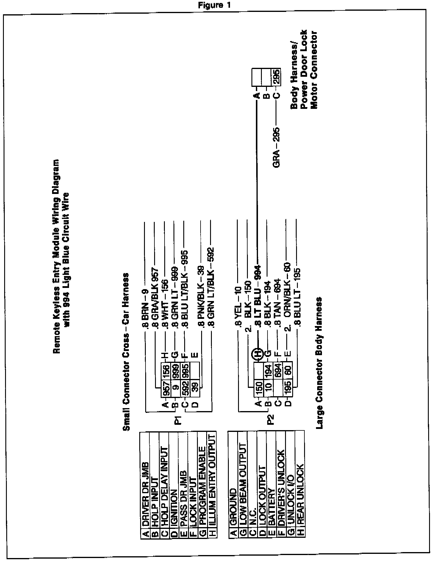
3. Disconnect the body wire harness connector (the larger connector) located on the right side of the remote keyless entry module (See Figure 1).
4. Crimp a 12034046 terminal to a 20 ft (7m) length of light blue 18 gauge (0.8 mm) wire and insert into the vacant "H" cavity of the connector.
5. Reconnect the body harness to the remote keyless entry module. E94 ONLY Remove door sill plate, stepwell pads and rear quarter trim panel.
6. Route wire under carpet along floor panel and secure with duct tape.
7. Locate body harness/power door lock motor harness connector at the right "D" pillar.
8. Crimp a 12047787 terminal to the light blue 18 gauge (0.8 mm) wire.
9. Remove the tan wire terminal from the "A" cavity of the body harness connector, remove the terminal and tape back the wire.
10. Insert the light blue 18 gauge (0.8 mm) wire terminal into the "A" cavity of the body harness connector.
11. Reconnect body harness to the power door lock motor harness.
12. Connect negative battery cable.
13. Reinstall the keyless entry module.
14. Check and verify proper operation of the circuit.
15. E94 ONLY Reinstall door sill plate, stepwell pads and rear quarter trim panel.
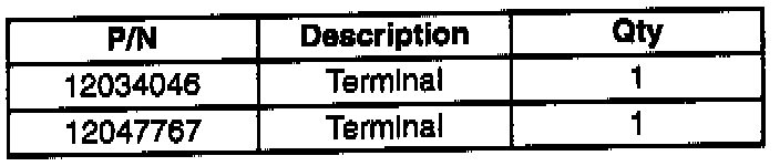
PARTS INFORMATION
Parts are currently available from GMSPO.
WARRANTY INFORMATION
For vehicles repaired under warranty, use:
Labor Operation Description Labor Time
Module Replace Use Published
N4821 Automatic Door Labor Operation
Locking System Time