Intermittent Wiper System
To diagnose system malfunctions that do not involve the delay function, refer to TWO SPEED WIPER SYSTEM. Wipers Run Without Delay With Switch In Delay PositionEXCESS DELAY OR INADEQUATE VARIATION IN DELAY
1. Variations in delay should be as follows:
a. Minimum delay: delay control to extreme right position before first detent, one half to two seconds.
b. Maximum delay: delay control to extreme left position before off detent, ten to thirty seconds.
2. If there is excessive delay or no variations in delay, replace wiper switch.
Fig. 4 Intermittent Wiper Control 8 Cavity Connector:

WIPERS DO NOT OPERATE, SWITCH IS IN DELAY POSITION
1. Disconnect wire connector from intermittent wiper control unit.
2. Place wiper switch in maximum delay position.
3. Connect volt meter between cavity 4 and cavity 6 on wire connector.
4. If volt meter reading is zero, check wiper switch and wiring.
5. If volt meter reading is 10 to 15 volts, place column switch in low position and connect voltmeter between cavity 3 and 4. If voltmeter reads 10-15 volts, control unit is faulty and should be replaced. If no voltage, check wiring.
WIPERS DO NOT RUN CONTINUALLY WHEN WASHER CONTROL IS OPERATED DURING DELAY MODE
1. Disconnect wire connector from intermittent control unit.
2. Connect a voltmeter between cavity 4 and cavity 7 on wire connector.
3. Depress washer switch, if voltmeter reading is zero, check switch and wiring.
4. If voltage reading is 10 to 15 volts, control unit is faulty and should be replaced.
WIPERS CONTINUALLY RUN WHEN WASHER IS OPERATED BUT DO NOT PROVIDE AN EXTRA WIPE WHEN WASHER CONTROL IS RELEASED
1. If this condition is encountered, replace the control unit.
WIPERS IMMEDIATELY GIVE FIRST WIPE, BUT DO NOT OPERATE WITH SWITCH IN DELAY MODE
1. Disconnect wire connect from intermittent control unit and check for bent contacts.
2. Place panel wiper switch in maximum delay position.
3. Connect a volt meter between cavity 4 and cavity 8 on wire connector.
4. If volt meter reading is zero, check wiper switch and wiring.
5. If volt meter reading is 10 to 15 volts, control unit is faulty and should be replaced.
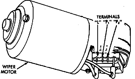
Fig. 2 Intermittent Wiper Motor Terminal Locations:

Fig. 3 Wiper Motor Terminal Location:
WIPERS RUN WITH OUT DELAY WITH SWITCH IN DELAY POSITION
1. On models with concealed wipers, proceed as follows:
a. Place wiper switch in low position and disconnect electrical connector to dwell switch.
b. Connect ohmmeter between dwell switch terminal and ground. Meter should indicate continuity once per wipe cycle.
c. If meter does not indicate continuity as specified, repair or replace dwell switch and recheck system. If meter indicates constant continuity, bend dwell switch contacts outward; if meter indicates no continuity, bend contacts inward.
d. If meter indicates continuity as specified, disconnect 8 cavity connector at control unit and check for battery voltage at cavity 5 in connector.
e. If voltage is present, replace control unit. If there is no voltage, check wiring and switch and repair as needed.
2. On models equipped with non-concealed wiper system, proceed as follows:
a. Verify that motor will return to park position when control switch is turned off.
b. Turn control switch to low position, then disconnect 8 wire connector from intermittent wipe control unit and inspect contacts for damage.
c. Connect test lamp between cavities 1 and 3 of connector. Lamp should light once during each wipe cycle.
d. If lamp lights intermittently, replace control unit. If lamp does not light, connect test lamp between motor terminals P1 and P2.
e. If lamp lights intermittently, check motor wiring.
WIPERS START ERRATICALLY WHEN IN DELAY MODE
1. Verify good ground at instrument panel, motor ground strap and intermittent control unit.
2. If grounds are satisfactory and condition persists, replace control unit.