Installation
INSTALLATION
NOTE: To ease and attain proper installation of the bushing using Special Tool 8405, use Mopar(R) Rubber Bushing Installation Lube as indicated in the following step.
1. Apply Mopar(R) Rubber Bushing Installation Lube to the outside edges of the NEW bushing. Also, lubricate the inside of Installer, Special Tool 8405-2, with the special lube.

2. Place the stepped end of Installer (3), Special Tool 8405-2, on the end of the trailing arm bushing sleeve (2) that has the curved flange (6) at the arm.
3. Place the lubricated bushing (4) inside the large opening in the Installer (3).
4. Place the Press (7), Special Tool C-4212F, with Receiver (1), Special Tool 8405-1, installed, over the arm (2), Installer (3) and bushing (4) as shown. When properly installed, the Press screw-drive (5) will be toward the center of the vehicle. Note the curve on the axle trailing arm (6). This curve prevents the tool from being properly installed in the opposite direction.
5. Using hand tools, slowly tighten the Press screw-drive (5), pressing the bushing into the trailing arm sleeve. Do not over-install the bushing; the bushing can be pushed out the other side if care is not used. Push the bushing in until freed from the installer (3) and centered in the trailing arm sleeve. The outer lips of the bushing must hang out past the end of the sleeve on each side of the trailing arm.
6. Remove the tools from the trailing arm.
7. If the opposite side bushing needs to be installed, repeat STEP 1 through STEP 6 on that side of the vehicle.

8. Install the trailing arm forward bracket(s) (2) on the axle in the following way:
a. From above the axle (4), place the bracket (2) down over the axle trailing arm bushing aligning the hole in the bracket with the center hole in the bushing.
b. From the outboard side of the axle and bracket, push the thru-bolt (1) through the bracket and bushing. The trailing arm bracket thru-bolts must be installed from the outside, in toward the center of the axle assembly, otherwise the bolt threaded ends will come in contact with the body of the vehicle upon axle installation on vehicle.
c. Install the nut (3) on the inboard end of the bolt. Tighten the nut until the bracket has resistance when turned, but still moves independent of the axle bushing. Do not tighten at this time; it must be fully tightened with the vehicle at curb height.
9. Remove the wood block between the arm and body of the vehicle.

10. Swing the axle trailing arms up aligning the brackets (3) with the scribed marks made upon removal.
11. Install all eight (four per side) axle bracket-to-body mounting bolts (4). Thread the bolts in, but do not fully tighten at this time.
12. Tap the brackets (3) as necessary to align the brackets with the scribed marks, then tighten all the bolts to 54 Nm (40 ft. lbs.).
13. Remove the jack.

CAUTION: When installing the watts links and bell crank to the axle, make sure the bell crank is right-side-up. When mounted properly, the words "BACK UP" (1) should be able to be read from the rear over the top of the axle.
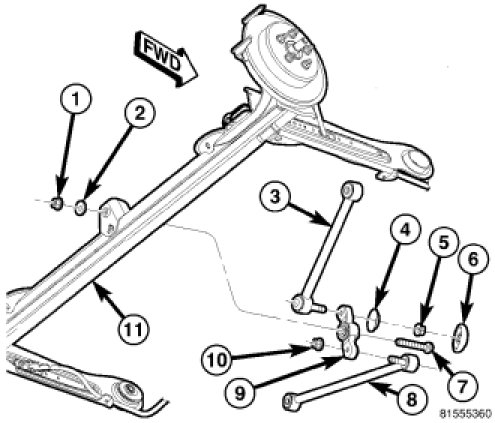
14. Install the bolt (7) from the front securing the watts link bell crank (9) to the center of the axle (11). Place the washer (2) and nut (1) on the end of the mounting bolt and tighten it to 149 Nm (110 ft. lbs.).
NOTE: Perform STEP 15 through STEP 19 on each side of the vehicle.

15. Move the parking brake cable (1) to its original mounting position below the axle pivot bushing on the inboard side of the trailing arm (2).
16. Align the cable routing brackets with their mounts on the trailing arm. Install the two bolts (3) securing the cable and routing brackets to the trailing arm (2). Tighten the mounting bolts to 11 Nm (100 in. lbs.).
17. Make sure the parking brake cable and grommet is still in the proper position at the body access hole.

18. Install the screw (2) securing the brake flex hose bracket (and wheel speed sensor cable if equipped) (1) to the vehicle body above the leading end of the axle trailing arm (3).

19. Install tire and wheel assembly (1) Tires and Wheels - Installation. Install and tighten wheel mounting nuts (3) to 135 Nm (100 ft. lbs.).
20. Lower the vehicle.
21. Place the vehicle on an alignment rack or drive-on hoist.
22. With the vehicle at curb height, tighten both trailing arm to mounting bracket pivot thru-bolts (1) to 122 Nm (90 ft. lbs.).