Removal
REMOVAL
NOTE: Before proceeding, Rear Suspension.
1. Raise and support the vehicle. Service and Repair
NOTE: Perform STEP 2 through STEP 5 on each side of the vehicle.

2. Remove the wheel mounting nuts (3), then the rear tire and wheel assembly.

3. Remove the screw (2) securing the rear brake flex hose (and wheel speed sensor cable if equipped) routing bracket (1) to the vehicle body above the leading end of the axle trailing arm (3).

4. Remove the two bolts (3) on the axle trailing arm securing the parking brake cable (1) and routing brackets to the axle trailing arm (2).
5. Move the parking brake cable (1) from its mounted position away from the bottom of the trailing arm bushing and the forward bracket.
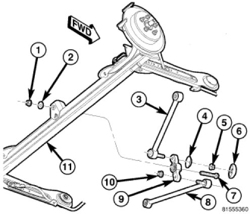
6. Remove the bolt (7), nut (1) and washer (2) securing the watts link bell crank (9) to the center of the axle (11).
7. Position a transmission jack or equivalent under the center of the axle raising it just enough to support the axle.

8. Using an awl (2), scribe a line (1) marking the location of one axle trailing arm bracket (3), side-to-side and front-to-rear, on the body of the vehicle. Perform this for the bracket on the opposite side of the vehicle as well.

9. Remove the bolts (4) securing both trailing arm forward brackets (3) to the body (2) of the vehicle.
10. Using the lower shock mounts as a pivot point, pry down on the forward end of the trailing arms and place a block of wood between the top of the arms and the body of the vehicle just to the rear of the forward mounting bracket. Be careful not to pinch any hoses or cables.

11. Remove the nut (3) and thru-bolt (1) fastening the trailing arm forward bracket (2) to the axle trailing arm bushing requiring service.

12. Place Receiver (1), Special Tool 8405-1, on Press (6), Special Tool C-4212F, and tighten the set-screw.
13. Place the special tool assembly over the bushing (3) as shown. When properly installed, the Press screw-drive (4) will be toward the center of the vehicle. Note the curve on the axle trailing arm (5). This curve prevents the tool from being properly installed in the opposite direction.
14. Tighten the Press screw-drive (4), pressing the bushing (3) out of the trailing arm (2) into the Receiver (1).
15. Remove the tool and the bushing from the trailing arm. Discard the used bushing.
16. If the opposite side bushing needs to be removed, repeat STEP 11 through STEP 15 on the opposite bushing.