Component Tests and General Diagnostics
CHECKING THE COOLING FAN OPERATION
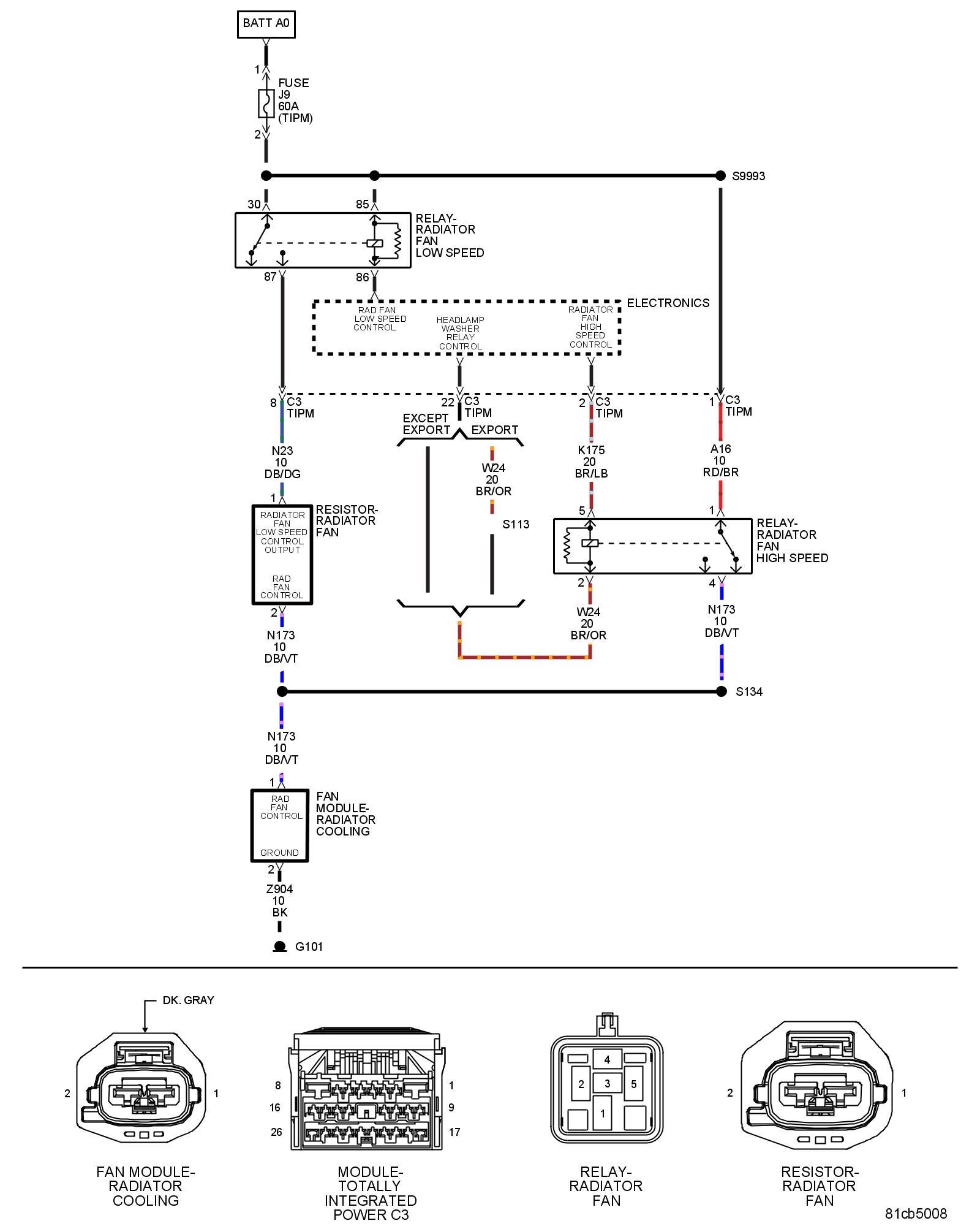
For a complete wiring diagram, refer to the Wiring Information .
1. RADIATOR FAN HIGH SPEED RELAY OPERATION
NOTE: Diagnose and repair any Coolant Fan circuit or Temperature Sensor circuit DTCs before proceeding with this test.
1. Turn the ignition on.
2. With the scan tool, actuate the Radiator Fan 2 control state.
Does the Cooling Fan operate?
Yes
- Go To 2
No
- Go To 3
2. RADIATOR FAN LOW SPEED RELAY OPERATION
1. With the scan tool, actuate the Radiator Fan 1 control state.
Does the Cooling Fan operate?
Yes
- Test complete.
No
- Go To 8
3. RADIATOR FAN HIGH SPEED RELAY
1. Turn the ignition off.
2. Verify the Radiator Fan High Speed Relay is installed properly and that the terminals are making a tight fit.
3. Remove the Radiator Fan High Speed Relay and substitute it with a known good Relay.
4. Ignition on, engine not running.
5. With a scan tool, actuate the Radiator Fan 2 control state.
Is the Cooling Fan operating?
Yes
- Replace the Radiator Fan High Speed Relay.
- Perform the BODY VERIFICATION TEST. Body Verification Test.
No
- Go To 4
4. (Z904) GROUND CIRCUIT OPEN
1. Turn the ignition off.
2. Disconnect the Radiator Cooling Fan Module harness connector.
3. Using a 12-volt test light connected to voltage, check the (Z904) Ground circuit in the Cooling Fan Module harness connector.
NOTE: The test light should be illuminated and bright. Compare the brightness to that of a direct connection to the battery.
Is the test light illuminated and bright?
Yes
- Go To 5
No
- Repair the (Z904) Ground circuit for an open or high resistance.
- Perform the BODY VERIFICATION TEST. Body Verification Test.
5. RADIATOR COOLING FAN MODULE
1. Turn the ignition on.
2. Using a 12-volt test light connected to ground, check the (N173) Radiator Fan Control circuit in the Radiator Cooling Fan Module harness connector.
3. With the scan tool, actuate the Radiator Fan 2 control state.
NOTE: The test light should be illuminated and bright. Compare the brightness to that of a direct connection to the battery.
Is the test light illuminated and bright?
Yes
- Replace the Cooling Fan.
- Perform the BODY VERIFICATION TEST. Body Verification Test.
No
- Go To 6
6. (N173) RAD FAN CONTROL CIRCUIT OPEN OR HIGH RESISTANCE
1. Turn the ignition off.
2. Remove the Radiator Fan High Relay.
3. Turn the ignition on.
4. Using a 12-volt test light connected to voltage, check the (A16) Fused B+ circuit in the Radiator Fan High Relay harness connector.
NOTE: The test light should be illuminated and bright. Compare the brightness to that of a direct connection to the battery.
Is the test light illuminated and bright?
Yes
- Repair the (N24) Rad Fan Control Relay Output circuit for an open or high resistance.
- Perform the BODY VERIFICATION TEST. Body Verification Test.
No
- Go To 7
7. (A16) FUSED B+ CIRCUIT OPEN OR HIGH RESISTANCE
1. Turn the ignition off.
2. Disconnect the C3 TIPM harness connector.
3. Measure the resistance in the (A16) Fused B+ circuit from the Radiator Fan High Speed Relay harness connector to the Totally Integrated Power Module (TIPM) harness connector.
Is the resistance below 100 Ohms?
Yes
- Go To 13
No
- Repair the (A16) Fused B+ circuit for an open or high resistance.
- Perform the BODY VERIFICATION TEST. Body Verification Test.
8. RADIATOR FAN LOW SPEED RELAY
1. Turn the ignition off.
2. Verify the Radiator Fan Low Speed Relay is installed properly and that the terminals are making a tight fit.
3. Remove the Radiator Fan Low Speed Relay and substitute it with a known good Relay.
4. Ignition on, engine not running.
5. With a scan tool, actuate the Radiator Fan 1 control state.
Is the Cooling Fan operating?
Yes
- Replace the Radiator Fan Low Speed Relay.
- Perform the BODY VERIFICATION TEST. Body Verification Test.
No
- Go To 9
9. RADIATOR COOLING FAN MODULE
1. Turn the ignition off.
2. Disconnect the Radiator Cooling Fan Module harness connector.
3. Turn the ignition on.
4. Using a 12-volt test light connected to ground, check the (N173) Radiator Fan Control circuit in the Radiator Cooling Fan Module harness connector.
5. With the scan tool, actuate the Radiator Fan 1 control state.
NOTE: The test light should be illuminated and bright. Compare the brightness to that of a direct connection to the battery.
Is the test light illuminated and bright?
Yes
- Replace the Cooling Fan.
- Perform the BODY VERIFICATION TEST. Body Verification Test.
No
- Go To 10
10. RADIATOR FAN CONTROL RELAY OUTPUT
1. Turn the ignition off.
2. Disconnect the Radiator Fan Resistor harness connector.
3. Turn the ignition on.
4. Using a 12-volt test light connected to ground, check the (N23) Radiator Fan Low Speed Control Output circuit in the Radiator Fan Resistor harness connector.
5. With the scan tool, actuate the Radiator Fan 1 control state.
NOTE: The test light should be illuminated and bright. Compare the brightness to that of a direct connection to the battery.
Is the test light illuminated and bright?
Yes
- Go To 11
No
- Go To 12
11. (N24) RAD FAN CONTROL RELAY OUTPUT OPEN OR HIGH RESISTANCE.
1. Turn the ignition off.
2. Measure the resistance in the (N24) Rad Fan Control Relay Output circuit from the Cooling Fan harness connector to the Radiator Fan Resistor harness connector.
Is the resistance below 100 Ohms?
Yes
- Replace the Radiator Fan Resistor.
- Perform the BODY VERIFICATION TEST. Body Verification Test.
No
- Repair the open or high resistance in the (N24) Rad Fan Control Relay Output circuit.
- Perform the BODY VERIFICATION TEST. Body Verification Test.
12. (N23) RADIATOR FAN LOW SPEED CONTROL OUTPUT CIRCUIT OPEN OR HIGH RESISTANCE
1. Turn the ignition off.
2. Disconnect the C3 TIPM harness connector.
3. Measure the resistance in the (N23) Radiator Fan Low Speed Control Output circuit from the Radiator Fan Resistor harness connector to the C3 TIPM harness connector.
Is the resistance below 100 Ohms?
Yes
- Go To 13
No
- Repair the open or high resistance in the (N23) Radiator Fan Low Speed Control Output circuit.
- Perform the BODY VERIFICATION TEST. Body Verification Test.
13. TOTALLY INTEGRATED POWER MODULE (TIPM)
1. Using the wiring diagram/schematic as a guide, inspect the wiring and connectors between the Cooling Fan Module, TIPM and the Powertrain Control Module (PCM).
2. Look for any chafed, pierced, pinched or partially broken wires.
3. Look for broken, bent, pushed out or corroded terminals. Verify that there is good pin to terminal contact in the Cooling Fan Module, TIPM and Powertrain Control Module (PCM) connectors.
4. Perform any Technical Service Bulletins (TSBs) that may apply.
Were there any problems found?
Yes
- Repair as necessary.
- Perform the BODY VERIFICATION TEST. Body Verification Test.
No
- Replace the Totally Integrated Power Module (TIPM).
- Perform the BODY VERIFICATION TEST. Body Verification Test.