P0627
P0627-FUEL PUMP CONTROL CIRCUIT
Special Tools:

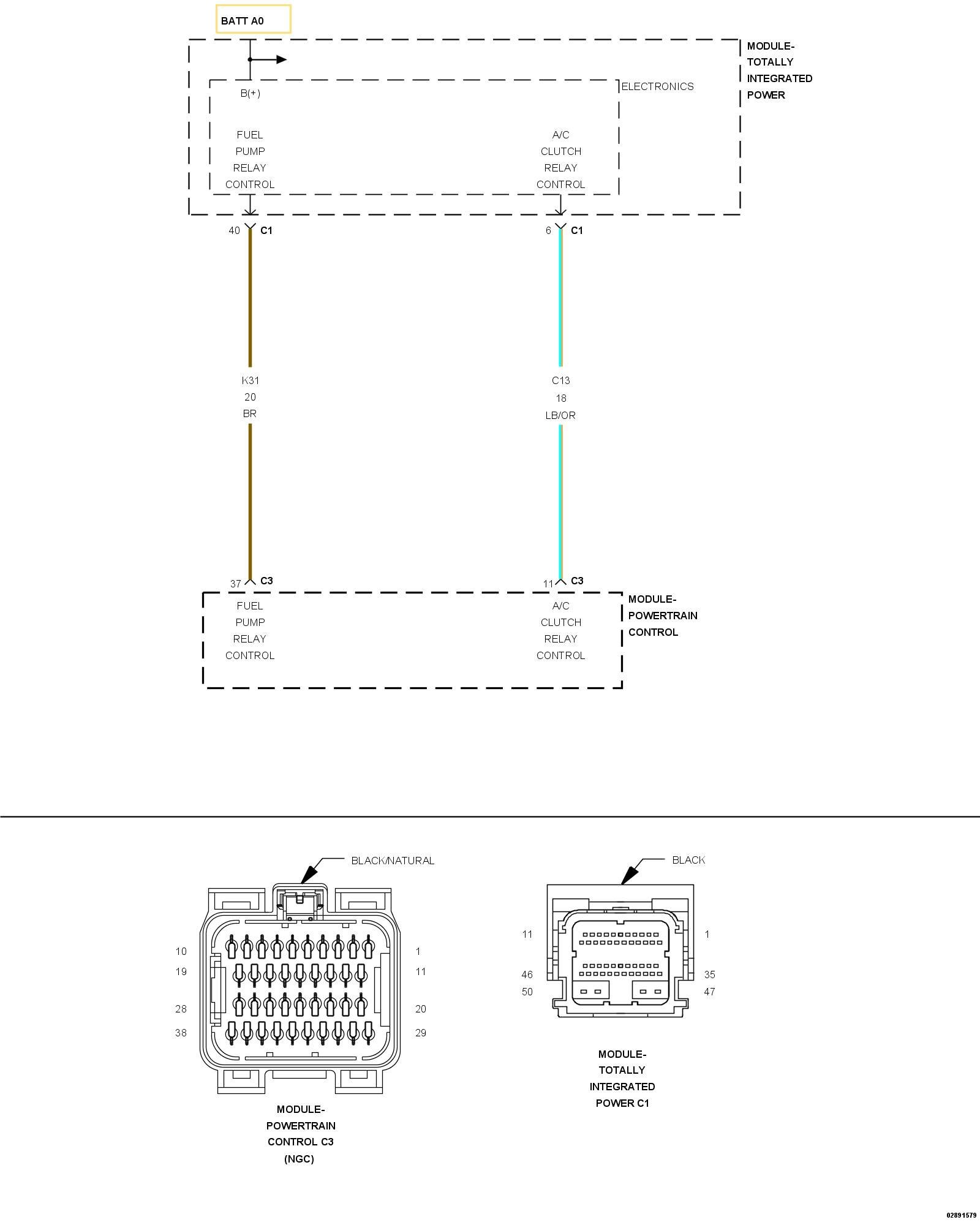
For a complete wiring diagram, refer to the Wiring Information.
Theory of operation
The Fuel Pump control is requested by the Powertrain Control Module (PCM) along the Fuel Pump control relay circuit. The Totally Integrated Power Module (TIPM) monitors the sense voltage on the Fuel Pump relay circuit, when PCM pulls the circuit low the TIPM engages the Fuel Pump. If the sense voltage is open or pulled low the PCM will set the P0627-FUEL PUMP RELAY CIRCUIT DTC.
- When Monitored:
With the ignition on. Battery voltage greater than 10.4 Volts and the ASD sense switch is on.
- Set Condition:
Actual Fuel Pump state is not equal to desired state. One Trip Fault. Three good trips to turn off the MIL.

Always perform the Pre-Diagnostic Troubleshooting procedure before proceeding. Pre-Diagnostic Troubleshooting Procedure.
1. DTC IS ACTIVE
NOTE: If there are any ASD/Main Relay or system voltage DTCs present, diagnose those DTCs before proceeding with this test procedure.
1. Ignition on, engine not running.
2. With the scan tool, select View DTCs. Copy DTC and Freeze Frame information and clear DTCs.
NOTE: Active or pending DTCs may not allow Fuel Pump actuation, make sure all DTCs are cleared before proceeding with this test procedure.
3. With the scan tool, actuate the Fuel Pump.
4. Monitor the scan tool for at least two minutes.
5. With the scan tool, select View DTCs.
Is the status Active for this DTC?
Yes
- Go To 2
No
- Perform the INTERMITTENT CONDITION diagnostic procedure. . Intermittent Condition Test
2. (K31) FUEL PUMP RELAY CIRCUIT SHORTED TO GROUND

1. Turn the ignition off.
2. Disconnect the C1 Totally Integrated Power Module (TIPM) harness connector.
3. Disconnect the C3 Powertrain Control Module (PCM) harness connector.
4. Measure the resistance between ground and the (K31) Fuel Pump Control circuit in the C1 Totally Integrated Power Module (TIPM) harness connector.
Is the resistance below 100 Ohms?
Yes
- Repair the short to ground in the (K31) Fuel Pump Control circuit.
- Perform the POWERTRAIN VERIFICATION TEST. Powertrain Verification Test.
No
- Go To 3
3. (K31) FUEL PUMP RELAY CIRCUIT OPEN OR HIGH RESISTANCE

CAUTION: Do not probe the PCM harness connectors. Probing the PCM harness connectors will damage the PCM terminals resulting in poor terminal to pin connection. Install the PCM Pinout Box to perform the diagnostics.
1. Measure the resistance of the (K31) Fuel Pump Control circuit between the Totally Integrated Power Module (TIPM) harness connector and the appropriate terminal of PCM Pinout Box.
Is the resistance below 5.0 Ohms?
Yes
- Go To 4
No
- Repair the open or high resistance in the (K31) Fuel Pump Control circuit.
- Perform the POWERTRAIN VERIFICATION TEST. Powertrain Verification Test.
4. TOTALLY INTEGRATED POWER MODULE (TIPM) ACTUATION

1. Connect the C1 Totally Integrated Power Module (TIPM) connector.
2. Turn the ignition on.
CAUTION: Do not probe the PCM harness connectors. Probing the PCM harness connectors will damage the PCM terminals resulting in poor terminal to pin connection. Install the PCM Pinout Box to perform the diagnostics.
3. Using a 12-volt test light connected to ground, probe the (K31) Fuel Pump Control circuit at the appropriate terminal of PCM Pinout Box.
NOTE: The test light should be illuminated and bright. Compare the brightness to that of a direct connection to the battery.
Is the test light illuminated and brightly?
Yes
- Go To 6
No
- Go To 5
5. TOTALLY INTEGRATED POWER MODULE (TIPM)
1. Using the wiring diagram/schematic as a guide, inspect the wiring and connectors between the Totally Integrated Power Module (TIPM) and the Powertrain Control Module (PCM).
2. Look for any chafed, pierced, pinched or partially broken wires.
3. Look for broken, bent, pushed out or corroded terminals. Verify that there is good pin to terminal contact in the related connectors.
4. Perform any Technical Service Bulletins that may apply.
Were any problems found?
Yes
- Repair as necessary.
- Perform the POWERTRAIN VERIFICATION TEST. Powertrain Verification Test.
No
- Replace the Totally Integrated Power Module (TIPM).
- Perform the BODY VERIFICATION TEST. Body Verification Test.
6. POWERTRAIN CONTROL MODULE (PCM)
1. Using the wiring diagram/schematic as a guide, inspect the wiring and connectors between the Totally Integrated Power Module (TIPM) and the Powertrain Control Module (PCM).
2. Look for any chafed, pierced, pinched or partially broken wires.
3. Look for broken, bent, pushed out or corroded terminals. Verify that there is good pin to terminal contact in the related connectors.
4. Perform any Technical Service Bulletins that may apply.
Were any problems found?
Yes
- Repair as necessary.
- Perform the POWERTRAIN VERIFICATION TEST. Powertrain Verification Test.
No
- Replace and program the Powertrain Control Module (PCM).
- Perform the POWERTRAIN VERIFICATION TEST. Powertrain Verification Test.