Air (BARO) Pressure and Manifold Pressure Parameters
AIR (BARO) PRESSURE, MANIFOLD PRESSURE, AND TURBOCHARGER PARAMETERSTHEORY
These parameters indicate ambient air pressure and high or low pressure inside the intake manifold. They are major input parameters used by the logic module to control the air-fuel ratio.
The engine control system must measure the atmospheric air pressure and the pressure in the intake manifold to determine engine load and calculate fuel metering and spark advance. Three pressure measurements or calculations usually are necessary:
- Barometric pressure is the ambient atmospheric air pressure. Barometric pressure changes with attitude and temperature. Standard barometric pressure at sea level is 14.7 psi, 101.3 kPa, or 29.9 "Hg.
- Manifold vacuum is the pressure in the intake manifold below atmospheric pressure when the engine is running. Manifold vacuum is measured in relation to atmospheric pressure. High vacuum is low pressure.
- Manifold absolute pressure (MAP) is the combination of atmospheric pressure and vacuum, or the relative difference between air pressure outside the manifold and vacuum inside. MAP is measured in relation to zero pressure (high vacuum).
Relationship Of Pressures:
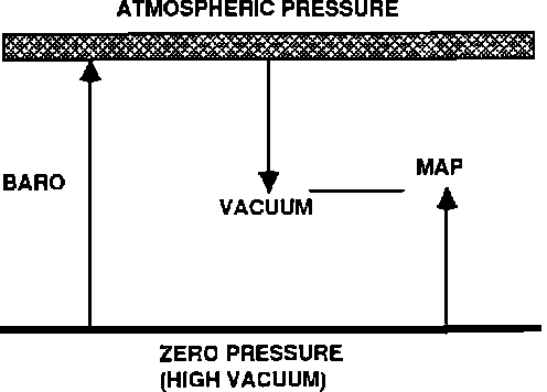
Barometric pressure (BARO), manifold vacuum, and MAP have the following relationships.
- MAP = BARO - vacuum
- Vacuum = BARO - MAP
- BARO = MAP + vacuum
Turbocharger boost operation also affects manifold pressure. When a turbocharger is providing boost pressure, manifold absolute pressure rises above atmospheric pressure.
Depending on the control system and sensors used on an engine, the scanner will display one or more of the MAP. BARO, or vacuum parameters. These are displayed as a voltage reading from the sensor and as a pressure measurement in either kilopascals (kPa) or inches of mercury ("Hg). You can change the pressure measurement units from one to the other. The preset measurements for all three values are in "Hg".
NOTE: The following paragraphs explain these parameters.
MANIFOLD ABSOLUTE PRESSURE SENSOR VOLTAGE
MAP SNSR(V) - X.X RANGE: 0 TO 5.1 VOLTS
The MAP sensor provides an analog voltage parameter that varies with manifold pressure. The voltage signal can range from 0 to 5.1 volts.
MAP is intake manifold pressure relative to zero. MAP and manifold vacuum are related inversely. For example:
- MAP voltage is low when absolute pressure is low (vacuum is high), such as during idle or deceleration.
- MAP voltage is high when absolute pressure is high (vacuum is low), such as during heavy load operation.
With the key on and engine off, the MAP sensor reads barometric pressure. The logic module uses this barometric pressure reading, along with the the MAP sensor voltage with the engine running, to calculate manifold vacuum and true absolute pressure. The logic module also uses MAP voltage and engine speed to calculate engine load.
MANIFOLD ABSOLUTE PRESSURE SENSOR VOLTAGE
MAP SNSR("Hg) - XXX RANGE: 0 to 60 "Hg
MAP SNSR(kPa) - XXX RANGE: 10 to 200 kPa
The logic module calculates a MAP reading from the MAP sensor voltage signal.
The MAP sensor reading should be about 29.9 "Hg or 100 to 102 kPa with the engine off and the manifold close to atmospheric pressure at sea level. When the engine is running with high manifold vacuum, the MAP reading will drop. A normally aspirated engine running at full throttle and full load has manifold pressure very close to atmospheric pressure. The MAP sensor reading should not be higher than about 29.9 Hg or 100 to 102 kPa. On a turbocharged engine, the reading will rise above 30 Hg or 100 kPa as boost is applied.
VOLTAGE HIGH LOW
MAP ("Hg") 21 18 15 12 9 6 3
MAP (kPa) 70 60 50 40 30 20 10
Compare the MAP voltage and MAP pressure readings on the scanner. Pressure should be high when voltage is high, low when voltage is low.
If the readings appear abnormal for the apparent engine load, the sensor signal to the logic module may be inaccurate or the logic module calculations may be incorrect for some reason.
BAROMETRIC PRESSURE READING
BARO PRESS("Hg) - XXX RANGE: 0 to 60 Hg
BARO PRESS(kPa) - XXX RANGE: 10 to 200 kPa
Chrysler systems do not have a separate BARO sensor, but the logic I module provides a BARO PRESS reading. The logic module first samples the MAP sensor with the key on and the engine off, just before cranking. At this point, manifold pressure should equal, or be very close to, atmospheric pressure.
Since 1985, Chrysler turbo systems have used a solenoid, called the "baro read" solenoid, to switch the MAP sensor inlet between atmospheric pressure and the intake manifold. Using the baro-read solenoid, the logic module updates the BARO readings when the engine is running by switching the sensor to the atmosphere during deceleration on some vehicles. Early 1985 systems updated the BARO readings by switching the MAP sensor to atmospheric pressure at idle.
The logic module uses the BARO pressure reading along with the MAP reading to calculate manifold vacuum and true absolute pressure. Although the measurement range is 0 to approximately 60 "Hg" or 10 to approximately 200 kPa, typical readings range from 29.6 "Hg (100 kPa) at sea level to about 17.8 "Hg (60 kPa) at 14,000 feet.
BAROMETRIC READ SOLENOID
BARO READ SOL - XXX RANGE: ON - OFF
On 1989 vehicles, this discrete parameter indicates that the logic module has energized the BARO READ solenoid. The BARO READ solenoid momentarily switches the MAP sensor inlet from manifold pressure to atmospheric pressure to update the barometric pressure reading for the logic module. When BARD READ SOL reads ON, the module is sampling barometric pressure. When it reads OFF, the MAP sensor is connected to the intake manifold to provide continuous manifold pressure readings to the logic module.
MANIFOLD VACUUM READING
MAN VAC ("Hg") - XXX RANGE: 0 to 60 "Hg"
MAN VAC (kPa) - XXX RANGE: 10 to 200 kPa
The logic module calculates a manifold vacuum reading from the MAP sensor voltage signal. It does this by comparing the barometric pressure (BARD PRESS) reading taken from the MAP sensor before start-up to the MAP voltage while the engine is running. The logic module converts the difference between the two voltage to a value that is equivalent to manifold vacuum (MAN VAC)
The reading should be about 0 "Hg or 0 kPa with the engine off and the manifold close to atmospheric pressure. When the engine is running with high manifold vacuum, the vacuum reading will increase. Although the scanner can display values up to 60 "Hg or 200 kPa, typical vacuum readings at idle are about 18 to 21 "Hg or 601070 kPa.
VACUUM HIGH VACUUM LOW VACUUM
VACUUM ("Hg") 21 18 15 12 9 6 3
VACUUM (kPa) 70 60 50 40 30 20 10
You can compare MAP and vacuum readings on the scanner, as follows:
- MAP voltage and pressure are high when vacuum is low.
- MAP voltage and pressure are low when vacuum is high.
BOOST PRESSURE GOAL
BOOST PRESS GOAL (PSI) - XXX RANGE: 1 to 30 psi
BOOST PRESS GOAL (kPa) - XXX RANGE: 10 to 200 kPa
On 1989 and later vehicles, BOOST PRESS GOAL indicates the level above barometric pressure at which the logic module is trying to maintain manifold pressure. That is, the parameter indicates the amount of desired turbocharger boost above atmospheric pressure. Typical readings will vary from model to model and should be much less than the scanner maximum display capabilities.
You can change the pressure measurement units from psi to kPa. The preset measurement is psi.
WASTEGATE ACTUATOR
WASTEGATE(%) - XXX RANGE: 0 to 100%
On some 1990 and later turbocharged vehicles, the logic module (SMEC or SBEC) controls the wastegate actuator through a pulse-width-modulated (PWM) solenoid. The solenoid modulates the pressure applied to the actuator and thus controls the wastegate opening.
WASTEGATE(%) is an analog parameter that indicates the percentage of on-time for the solenoid. It also indicates the amount of wastegate opening. The WASTEGATE(%) reading should be low at idle part throttle, or other tow-boost conditions. The percentage should be high under high boost pressure conditions.
WASTEGATE SOLENOID
WASTEGATE SOL - XXX RANGE: ON - OFF
The 1990 and later turbocharged vehicles that transmit an analog WASTEGATE(%) parameter also transmit a discrete signal that indicates whether the solenoid is off or being turned on by the SMEC or SBEC.
VNT SOL #1 - XXX
VNT SOL #1 - XXX RANGE: ON - OFF
VNT SOL #1 - XXX
Chrysler variable-nozzle-turbo (VNT engines do not have wastegates, but have three computer controlled solenoids to control turbo nozzle opening. These parameters indicate whether the SMEC or SBEC has turned the solenoids on or off. Solenoid 1 is turned either fully on or fully off; it is not pulse-width modulated.
VNT SOL #2(%) - XXX
RANGE: 0 - 100%
VNT SOL #3(%) - XXX
Solenoids 2 and 3 on VNT engines are pulse-width modulated by the SMEC or SBEC. These analog parameters indicate the percentage of on-time for each solenoid.