P0850
P0850-PARK/NEUTRAL SWITCH PERFORMANCE

For a complete wiring diagram refer to Diagrams/Electrical.
Theory of Operation
The Park Neutral switch rationality test is enabled only for vehicles equipped with a 4/5 speed automatic transmission. This diagnostic checks if the park/neutral switch is incorrectly stuck in the neutral position during driving conditions by comparing Vehicle Speed, Engine Speed, Throttle Position, and Pressure Ratio to the fail thresholds and by looking at the state of the Park/Neutral Switch. The stuck in drive condition is not explicitly checked as the starter relay does not energize and therefore render the vehicle inoperable.
- When Monitored:
Continuously with the transmission in Park, Neutral, or Drive and NOT in Limp-in mode.
- Set Condition:
This code will set if the PCM detects an incorrect Park/Neutral switch state for a given mode of vehicle operation. Two trip fault. Three good trips to turn off the MIL.

Always perform the Pre-Diagnostic Troubleshooting procedure before proceeding.
Diagnostic Test
1. P/N & D/R NOT IN CORRECT POSITION
NOTE: Check the TCM for DTCs, if P0706 is set in the TCM diagnose the TCM code before continuing.
Ignition on, engine not running.
With the scan tool, read the Park/Neutral Position Switch input state.
While moving the gear selector through all gear positions (Park to 1 and back to Park), monitor the scan tool display.
Did the scan tool display show P/N and D/R in the correct gear positions?
Yes
- Refer to the INTERMITTENT CONDITION Diagnostic Procedure. Intermittent Condition
No
- Go To 2
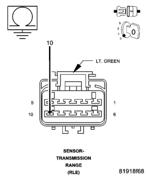
2. TRS (T41) SENSE (P/N SENSE) CIRCUIT OPEN

Turn the ignition off.
Disconnect the C3 PCM harness connector.
Disconnect the Transmission Range Sensor harness connector.
CAUTION: Do not probe the PCM harness connectors. Probing the PCM harness connectors will damage the PCM terminals resulting in poor terminal to pin connection. Install Miller Special Tool #8815 to perform diagnosis.
Measure the resistance of the TRS (T41) Sense (P/N Sense) circuit from the TRS harness connector to the appropriate terminal of special tool #8815.
Is the resistance below 5.0 ohms?
Yes
- Go To 3
No
- Repair the open in the TRS (T41) Sense (P/N Sense) circuit.
- Perform the POWERTRAIN VERIFICATION TEST. Powertrain Verification Test
3. TRS (T41) SIGNAL CIRCUIT SHORTED TO GROUND
Measure the resistance between ground and the TRS (T41) Sense (P/N Sense) circuit at the TRS harness connector.
Is the resistance above 100k ohms?
Yes
- Go To 4
No
- Repair the short to ground in the TRS (T41) Sense (P/N Sense) circuit.
- Perform the POWERTRAIN VERIFICATION TEST. Powertrain Verification Test
4. TRANSMISSION RANGE SENSOR
Measure the resistance between ground and the (T41) TRS Sense (P/N Sense) circuit while moving the gear selector through each gear in the TRS connector.
NOTE: The circuit is grounded in Park and Neutral and open in the other positions.
Did the resistance change from above 100k ohms (open) to below 10.0 ohms (grounded)?
Yes
- Go To 5
No
- Replace the Transmission Range Sensor.
- Perform the POWERTRAIN VERIFICATION TEST. Powertrain Verification Test
5. PCM
NOTE: Before continuing, check the PCM harness connector terminals for corrosion, damage, or terminal push out. Repair as necessary.
Using the schematics as a guide, inspect the wire harness and connectors. Pay particular attention to all Power and Ground circuits.
Were there any problems found?
Yes
- Repair as necessary.
- Perform the POWERTRAIN VERIFICATION TEST. Powertrain Verification Test
No
- Replace and program the Powertrain Control Module.
- Perform the POWERTRAIN VERIFICATION TEST. Powertrain Verification Test