Instrument Panel - Installation
INSTALLATION

NOTE: The instrument panel cannot be installed as an assembly, the instrument panel reinforcement must be installed prior to the instrument panel cover.
1. With the help of an assistant, position the instrument panel structure (2) into the vehicle. Make sure that all wiring harnesses are routed properly and are not pinched when installing the instrument panel structure.
2. Install the fasteners (1) through the body side securing the the instrument panel structure (2). Tighten the fasteners securely. Repeat for the opposite side.
3. Install the doors, Front Door - Installation.

4. Install the fasteners (1) securing the instrument panel structure to the dash/cowl panel. Tighten the fasteners securely.

5. Install the fasteners (2) securing the instrument panel structure (1) to the floor bracket. Tighten the fasteners securely.
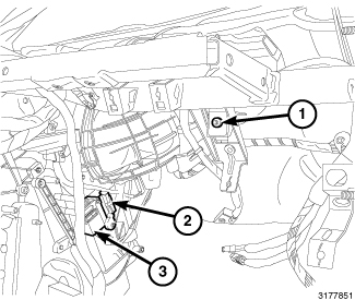
6. Install the fastener (1) securing the instrument panel structure (1) to the HVAC housing. Tighten the fastener securely.
7. Connect the HVAC wiring harness connectors (2, 3).

8. Locate and install the nut fastener located forward of the stud (1) securing the lower portion of the instrument panel structure to the HVAC. Tighten the fastener securely. Repeat for the opposite side.

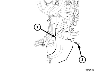
9. Connect the left connector (1) to the occupant restraint module.
10. Install the eyelet and ground fastener (2). Tighten the fastener securely.

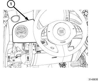
11. With the help of an assistant, position the instrument panel cover (1) into the vehicle and connect the two PAB squib connectors.

12. Install the fence bolt (1) located in the radio cavity. Tighten the bolt securely.

13. Install the fence bolt (1) located on the lower right area of the instrument panel. Tighten the bolt securely.

14. Install the fence bolt (1) located on the lower left area of the instrument panel. Tighten the bolt securely.

15. Install the fence bolt (1) located in the demister duct cavity. Tighten the bolt securely. Repeat on the opposite side.
16. Install the demister outlet vents on both sides.

17. Install the fence bolts (1) located in the defroster duct cavity. Tighten the bolt securely.

18. Install the passenger air bag bolts, Passenger Air Bag - Installation.
19. Position the glove box module (4) near the instrument panel cover and if equipped, connect any wiring harnesses.
20. Install the three screws (1) located on the top edge of the glove box module (4).
21. Install the bolt (2) located in the glove box cavity. Tighten the bolt securely.
22. Close the glove box door (3) and install the two screws securing the module to the instrument panel cover located on the bottom front edge of glove box module (4).

23. Install the center air outlet by engaging the two retaining tabs (1 and 3) that secure the top of the center air outlet (4) to the instrument panel (2).

24. Install the two screws (2 and 4) that secure the bottom of the center air outlet (1) to the instrument panel (3). Tighten the screws securely.
25. Install the radio, Radio - Installation.

26. Install the defroster grille (1) to the instrument panel.
27. Connect and install the navigation pod/port (2) to the instrument panel.

28. Install the instrument cluster, Instrument Cluster - Installation.
29. Position the cluster bezel (2).
30. Install the three screws (1) securing the cluster bezel (2).
31. Install the steering wheel and column shroud, Installation ,Steering Column Shroud - Installation.

32. Install the four screws (2, 3, 5 and 6) that secure the A/C heater control (1) to the instrument panel cover (4). Tighten the screws securely.

33. Position the center trim bezel (1) near the instrument panel cover and connect the harness to the switch pod.
34. Align the center trim bezel and hand tap to engage the retaining clips.
35. Install the center trim bezel retaining screws. Tighten the screws securely.

36. If required, lightly lubricate the control shafts to housing contact points on the front of the A/C heater control (1) using Silicone Grease, available through Mopar.
37. Turn all of the control shafts (4) on the A/C heater control to the full clockwise position.

38. If required, lightly lubricate the control knobs to control panel contact points on the back of the panel using Silicone Grease, available through Mopar.
39. Turn all of the control knobs on control panel (1) to the full clockwise position.

CAUTION: Proper alignment of the control knobs to the shafts on the A/C heater control is critical for reassembly. The knobs and shafts must be clocked correctly to each other or damage to the A/C heater control will result during reassembly.
40. Position the control panel (1) to the instrument panel (2) and align the control knobs to the control shafts and install the panel. Make sure the retaining tabs are fully engaged and that the controls move freely throughout the operating ranges.

41. Install the kneeblocker airbag (2), Knee Blocker Air Bag - Installation.
42. Position and align the closeout panel (1) the instrument panel. Once aligned, hand tap to engage the retaining clips.
43. Position and align the left side vent/trim panel (1) to the instrument panel. Once aligned, hand tap to engage the retaining clips.

44. Position and align the instrument panel closeout panel (2).
45. Install the instrument panel closeout fasteners (1).

46. Position the shifter hosing bezel (3).
47. Install the screws (1, 2) securing the shifter hosing bezel (3). Tighten the screws securely.

48. Position the shifter bezel (3) and connect the window switches (1) to their harnesses (4).
49. Align the shifter bezel (3) and hand tap to engage it's retaining tabs (2).

50. Connect the 12V power harness (3), position and align the front floor console (4) in the vehicle.
51. Install the retaining nuts (1) located in the cupholder cavity and in the rear of the front floor console (4). Tighten the retaining nuts securely.
52. Install the front cupholder insert (2).

53. Install the screw (1) securing the front console to shifter bezel cover. Tighten the screw securely. Repeat for the opposite side.

54. Position the left side closeout cover (1) and hand tap to engage the rear retaining tabs.
55. Install the screw (2) to the left side closeout panel (1). Tighten the screw securely.

56. Position the right closeout cover (1) into the vehicle push forward to engage the retaining clip in the floor.
57. Hand tap to engage the front floor console to closeout cover retaining clips.
58. Install the screw (2) to the right side console closeout cover (1). Tighten the screw securely.

59. Slide the rear floor console (1) over the parking brake handle and position into the vehicle.
60. Push the rear floor console forward to engage the front to rear floor console retaining clips/tabs.
61. Install the rear retaining nut (3) located in the rear cupholder cavity. Tighten the nut securely.
62. Install the rear cupholder insert (2).
63. Position the parking brake handle own fully.
64. Position the cowl/scuff panel (1) into the vehicle, engage the cowl/scuff panel (1) upper retaining clip by pushing rearward.
65. Install the front screw (3) to the cowl/scuff panel (1). Tighten the screw securely.
66. Repeat steps for the opposite side.

67. Starting at the front and working rearward, hand tap to engage the retaining clips (2 and 3).
68. Install the screw (4) located in the rear of the cowl/scuff panel (1). Tighten the screw securely.
69. Re-install the weatherstrip to the lower half of the door.
WARNING: Do not reconnect the battery without first performing the Airbag System Test procedure Component Tests and General Diagnostics . Failure to perform the Airbag System Test may result in accidental airbag deployment and serious or fatal injury.
70. Reconnect the negative battery cable.