Injection Pump - Updated Service Procedure
90ford03
^ INJECTION PUMP - 6.9L DIESEL ENGINE - SERVICE PROCEDURE FOR INSTALLING 7.3L LEVEL ADAPTER HOUSING WITH INTEGRAL OIL FILL TUBE
^ ENGINE - 6.9L DIESEL - INJECTION PUMP ADAPTER
KIT
Article No. 90-3-10
LIGHT TRUCK: 1985-87 E-250, E-350, F-250, F-350
ISSUE: The original 6.9L injection pump adapter housing and oil fill tube are no longer available. An injection pump adapter kit is now available that will allow you to install a 7.3L level adapter housing with an integral oil fill tube.
ACTION: If service is required, install an injection pump adapter kit (FOTZ-9C516-A). Refer to the following procedure for service details.
Figure 1:
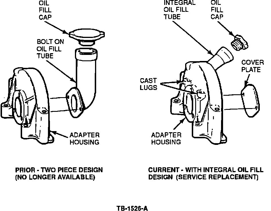
See Figure 1 for a comparison between the old and new injection pump adapter housing design. The new Injection Pump Adapter Kit (FOTZ-9C516-A) consists of:
^ Adapter Housing (with integral oil fill tube)
^ Injection Pump Gear Cover
^ Washers (2) for the gear cover
^ Bolts (2) for the gear cover - 5/16" 18 UNC x .75"
^ Oil Filler Cap Assembly and Plug, hex-head 3/4"- 16
^ Washers (3) 3/8" hardened; Belleville Washers
(3) 3/8"; Nuts (3) 3/8" - 16 hex
^ Fuel Return Tube Assembly, Fuel Return Hose And Hose Clamp
^ Elbow with 5/16" Hose Barb
^ Installation Instruction Sheet
REMOVAL
1. Remove the following components. Refer to the appropriate 1985-87 Light Truck Shop Manual, Section 22-08 for service details.
^ Fuel injection lines, disconnect at the nozzle ends
^ Oil fill tube
^ Injection pump drive gear mounting bolts
^ Electrical connections at pump
^ Fast idle solenoid bracket assembly.
2. Remove the fuel return line.
Early Models with a one-piece steel fuel return tube assembly.
a. Remove the fuel return pipe connector from the 90~ elbow at the governor cover.
Figure 2:
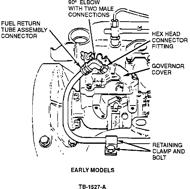
b. Disconnect the fuel return pipe retaining clamps. Remove the assembly and discard. See Figure 2.
c. Disconnect and discard the 90~ elbow from the governor cover. DO NOT remove the hex head connector fitting from the governor cover.
NOTE: IF EQUIPPED WITH A STEEL FUEL RETURN TUBE ASSEMBLY, DISCARD THE COMPONENTS DESCRIBED ABOVE AND INSTALL THE NEW COMPONENTS PROVIDED WITH THE KIT.
Later Models with a combination hose and tube, fuel return line assembly.
Figure 3:
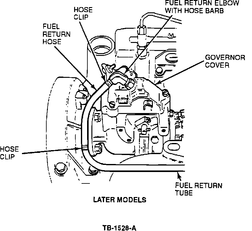
Disconnect the fuel return hose and clip from the 90~ elbow with the male 5/16" hose barb, Figure 3.
NOTE: IF EQUIPPED WITH A COMBINATION HOSE AND TUBE FUEL RETURN LINE ASSEMBLY, NO FURTHER REMOVAL OF THESE COMPONENTS IS REQUIRED. THE ENGINE IS EQUIPPED WITH THE SAME COMPONENTS WHICH ARE PROVIDED WITH THIS KIT. USE THE NEW FUEL RETURN COMPONENTS FROM THE KIT ONLY IF THE EXISTING COMPONENTS ARE DAMAGED. THE NEW ADAPTER HOUSING WILL FIT WITH THESE COMPONENTS.
3. Now remove the following components. Refer to the appropriate 1985-87 Light Truck Shop Manual, Section 22-08 for service details.
^ Fuel filter to injection pump tube
^ Pump inlet elbow
^ Injection pump assembly. (Discard old pump mounting hardware - Belleville washers, hardened washers and nuts.)
Figure 4:
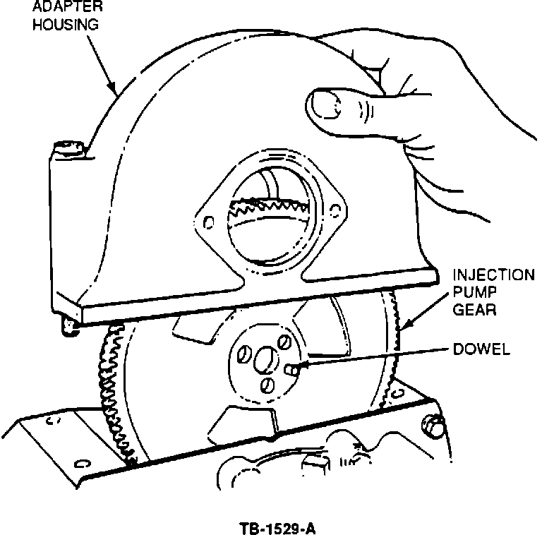
4. Remove the adapter housing bolts and adapter housing, Figure 4. Discard the housing, but retain the bolts. Clean the old RTV sealant from the crankcase and front cover.
NOTE: DO NOT DISTURB OR REMOVE THE INJECTION PUMP GEAR WHEN REMOVING THE ADAPTER HOUSING OR CLEANING OFF THE RTV SEALANT. IF THE INJECTION PUMP GEAR IS DISTURBED, REFER TO THE APPROPRIATE 1985-87 LIGHT TRUCK SHOP MANUAL, SECTION 22-08 FOR PROPER TIMING MARK ALIGNMENT PROCEDURE.
REASSEMBLY
1. Apply a 1/8" diameter bead of RTV sealant into the narrow groove at the bottom and sides of the new one-piece adapter housing. Also, apply a 3/16" diameter bead of RTV sealant across the front bottom groove of the adapter housing.
2. Install the adapter housing.
NOTE: ASSEMBLE COMPONENTS WITHIN 15 MINUTES OF RTV SEALANT APPLICATION. IF SEALANT "SETS UP", IT LOSES ITS SEALING EFFECTIVENESS.
Figure 5:
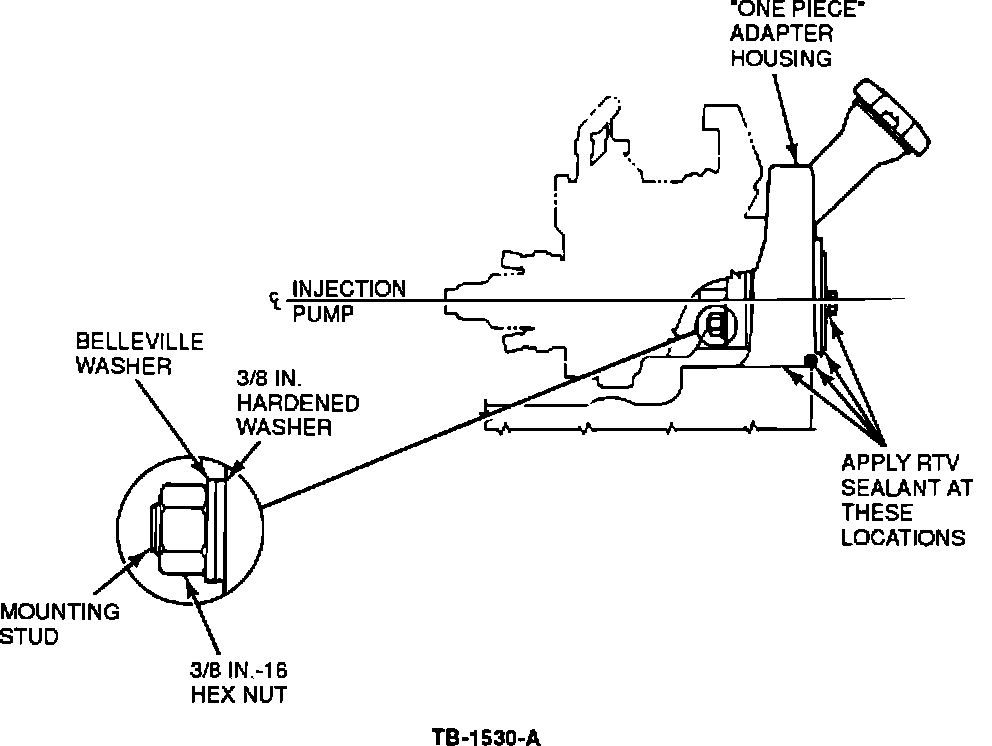
3. Install the injection pump using the three hardened washers, Belleville washers and nuts supplied in the kit, Figure 5. Use the injection pump wrench.
CAUTION: DO NOT REUSE OLD PUMP MOUNTING HARDWARE.
4. Install the adapter housing cover plate using the two 5/16" 18 UNC x .75" LG bolts and two washers included in the kit.
NOTE: APPLY RTV SEALANT TO THE COVER MOUNTING SURFACE AND TO THE BOLT THREADS, AS NECESSARY, PRIOR TO INSTALLATION. TIGHTEN BOLTS TO 14 FT.LB. (19 N-m). SEE FIGURE 5.
5. Remove all fuel system protective caps.
For early model engines equipped with a one-piece steel fuel return tube assembly, install the following components.
^ Fuel return tube assembly
^ Fuel return hose
^ Hose clamps
^ 90~ Elbow with 5/16" hose barb
NOTE: IF SERVICING AN ENGINE ALREADY EQUIPPED WITH A COMBINATION HOSE AND TUBE FUEL RETURN LINE ASSEMBLY, RECONNECT THOSE COMPONENTS AND DISCARD THE NEW PARTS PROVIDED IN THE KIT. REFER TO "REMOVAL" STEP # 2.
Install the following parts on all 6.9L engines.
^ Fuel filter to injection pump tube and pump inlet elbow
^ Fuel injection lines to nozzles.
6. Reinstall the fast idle solenoid bracket assembly to the injection pump.
NOTE: USE NEW RUBBER SEALING SLEEVES ON ALL FUEL LINE CONNECTORS EQUIPPED WITH SUCH SLEEVES.
INJECTION PUMP TIMING
1. Dynamically check pump timing. Refer to the Engine/Emissions Diagnosis Manual, Volume H, Section 24 for service procedure.
2. Adjust the injection pump timing.
a. Loosen the injection pump mounting nut by using the injection pump wrenches.
b. Rotate the injection pump clockwise (as viewed from the front of the engine) to retard timing.
c. Rotate the injection pump counterclockwise to advance timing.
d. Tighten the injection pump mounting nuts.
e. Start the engine.
f. Check pump timing.
Figure 6:
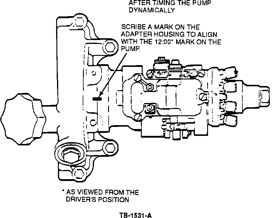
3. When the dynamic timing specifications are achieved, scribe a new alignment mark on the adapter housing at the 12 o'clock position after the pump is timed dynamically, Figure 6.
PART NUMBER PART NAME CLASS
FOTZ-9C516-A Injection Pump Adapter Kit C
OTHER APPLICABLE ARTICLES: None
WARRANTY STATUS: Eligible Under Basic Warranty Coverage, Powertrain Warranty Coverage
OPERATION DESCRIPTION TIME
900310A Install Adapter Kit - 4.1 Hrs.
Econoline
900310A Install Adapter Kit - F 2.4 Hrs.
Series
DEALER CODING
BASIC PART NO. CONDITION CODE
9F736 01
OASIS CODES: 4700, 4500