Fuel System (CNG/LPG) - No Start Condition
Article No.03-10-3
05/26/03
^ DRIVEABILITY - BI-FUEL CNG/LPG LOW FLOW
INJECTOR SERVICE KIT WITHOUT COOLANT LOCK-OFF
^ DRIVEABILITY - CRANK NO START - BI-FUEL
CNG/LPG VEHICLES - LOW FLOW INJECTOR
SERVICE KIT WITHOUT COOLANT LOCK-OFF
FORD:
1996-2000 CONTOUR
1996-2003 F-150
1997 F-250 LD
1998-1999 E SERIES
2000-2001 SUPER DUTY F SERIES
Article 02-10-5 is being republished in its entirety to update the model line and model year coverage.
ISSUE
Some 1996-2002 B-Fuel CNG F-150, E-250/350, 1996-2000 Contour, 2000-2003 B-Fuel LPG F-150 and 2000-2001 Super Duty F Series vehicles (without coolant lock-off) may exhibit a no start condition. This may be caused by stuck Low Flow Injectors on the Compuvalve possibly due to fuel contamination. To avoid the replacement of the Compuvalve when only the Low Flow Injectors have failed, the Low Flow Injectors have been released separately for service.
ACTION
If diagnosis leads to a failed Low Flow Injector, refer to the following removal and installation procedure to replace the Low Flow Injector assembly.
SERVICE PROCEDURE
WARNING
WHEN SERVICING FUEL RELATED COMPONENTS, ELIMINATE ALL SOURCES OF IGNITION (E.G. TORCHES, HEATERS, AND LIGHTED TOBACCO). FLAMMABLE MIXTURES MAY BE PRESENT AND CAN IGNITE, RESULTING IN DAMAGE AND/OR INJURIES. THE FUEL SYSTEM LINE PRESSURE MUST BE RELIEVED BEFORE ANY COMPONENT CAN BE REMOVED. REMOVAL OF COMPONENTS WITHOUT PRESSURE RELIEF CAN CAUSE AN UNCONTROLLED RELEASE OF PROPANE OR NATURAL GAS AND MAY RESULT IN DAMAGE AND/OR INJURIES.
PRELIMINARY PREPARATION
1. Relieve system line pressure and remove the Compuvalve from the vehicle. Refer to Service Manual GFIP162 for the 1996 CNG Bi-Fuel model year and Service Manual GFIP173 for the 1998 CNG Bi-Fuel model year. Bi-Fuel vehicles for the 1999 through 2003 Bi-Fuel CNG model years and 2000 through 2003 Bi-Fuel LPG model years. Refer to the Ford Truck/Car Workshop Manual Section 303-04D.
NOTE
ONCE THE SYSTEM IS DISCONNECTED, COVER ALL OPEN HOSE FITTINGS AND ELECTRICAL CONNECTIONS TO AVOID CONTAMINATION.
2. Ensure that all loose debris is removed from the injector area, to avoid contamination during removal.
3. Place the Compuvalve flat on a work bench (with injectors facing up).
NOTE
ENSURE THAT THE BENCH SURFACES ARE CLEAN AND DIRT FREE. BENCHES SHOULD BE COVERED TO AVOID SCRATCHING COMPONENT SURFACES.
REMOVAL OF LOW FLOW INJECTOR ASSEMBLY
NOTE
DURING THE REMOVAL OF THE LOW FLOW INJECTORS, CARE SHOULD BE TAKEN TO PREVENT ANY DEBRIS FROM ENTERING THE FUEL FLOW OPENINGS.
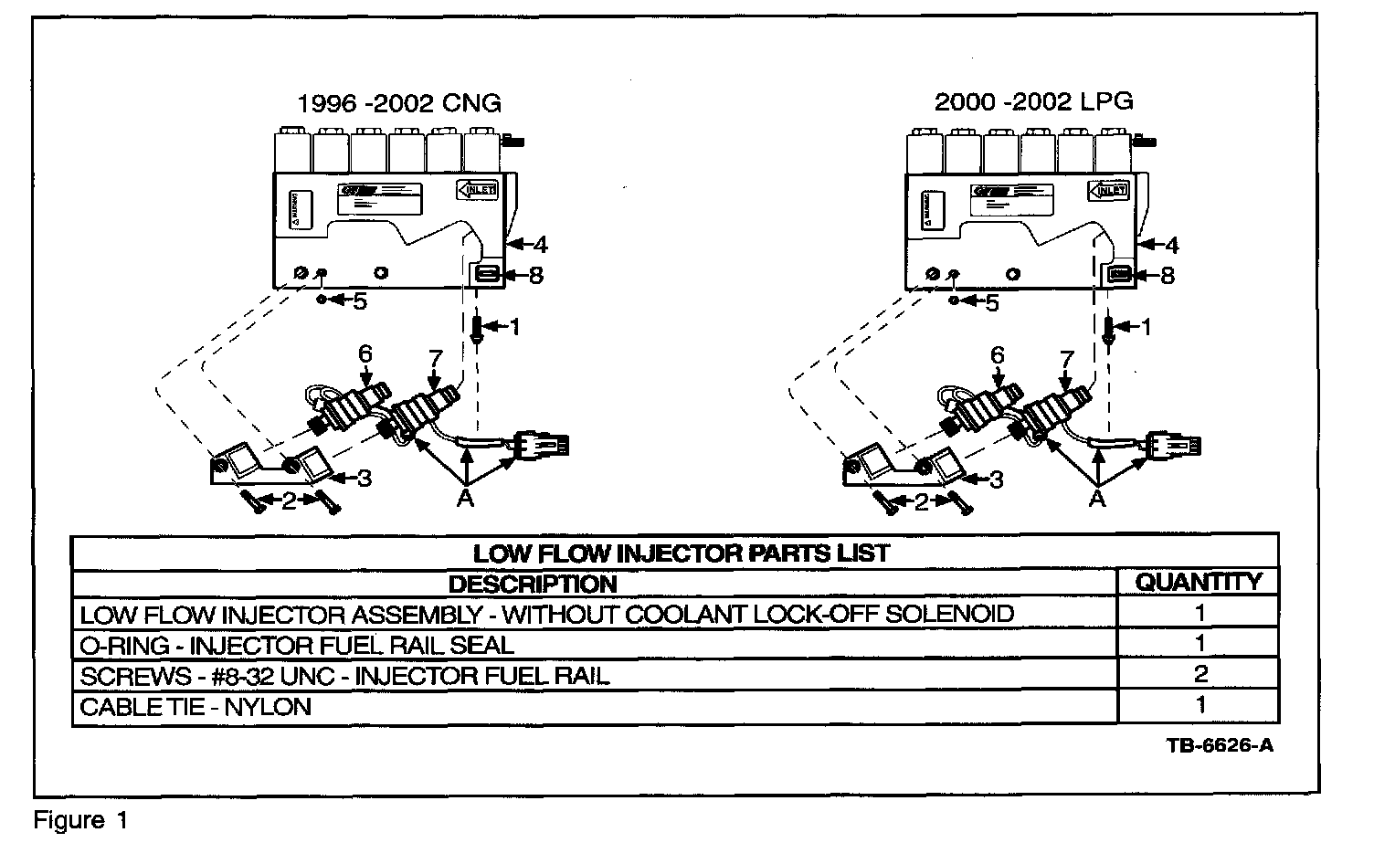
1. Carefully cut cable tie (1) securing the Low Flow Injector Assembly (A) harness and discard cable tie (Figure 1).
2. Remove the two mounting screws (2) securing the Injector Fuel Rail (3) to the Compuvalve (4) and discard screws (Figure 1).
3. Remove the Low Flow Injector Assembly (A) and Injector Fuel Rail (3) from Compuvalve (4). Discard Low Flow Injector assembly (A) and set aside the Injector Fuel Rail (3) (Figure 1).
4. Remove 0-ring (5) from Compuvalve (4) and discard 0-ring (Figure 1).
NOTE
IF THE COMPUVALVE IS LEFT UNINSTALLED FOR AN EXTENDED PERIOD OF TIME, USE A CLEAN LINT-FREE CLOTH TO COVER ALL EXPOSED OPENINGS TO AVOID CONTAMINATION.
INSTALLATION OF LOW FLOW INJECTOR ASSEMBLY
Assembly Preparation
1. Ensure all mating surfaces between Compuvalve (4), Injector Fuel Rail (3) and Low Flow Injectors (6) & (7) are clean (Figure 1).
NOTE
TO CLEAN, GENTLY WIPE SURFACES USING A CLEAN LINT-FREE CLOTH.
2. Ensure that lubricant is on both the inlet and outlet 0-rings of the new Low Flow Injectors (6) & (7) and on 0-ring (5) (Figure 1).
NOTE
IF REQUIRED, APPLY A THIN FILM OF NON-SILICONE BASED LUBRICANT FOR 0-RINGS (E.G. PARKER 0-LUBE).
3. Before installing the Low Flow Injector Assembly (A), ensure that the orientation of injector # 1 (6) (with shorter wire) and of injector # 2 (7) (with longer wire) are positioned as shown (Figure 1).
Assembly Installation
NOTE
DURING THE INSTALLATION OF THE LOW FLOW INJECTORS, CARE SHOULD BE TAKEN TO PREVENT ANY DEBRIS FROM ENTERING THE FUEL FLOW OPENINGS.
1. Press the outlet of the Low Flow Injectors (6) & (7) into Compuvalve (4) (Figure 1).
2. Route wires under the outlet portion of the Low Flow Injectors (6) & (7) 50 that the wires will not become pinched between Compuvalve (4) and the Injector Fuel Rail (3) (Figure 1)
3. Install 0-ring (5) into Compuvalve (4) as shown (Figure 1).
4. Press Injector Fuel Rail (3) onto the inlet of Low Flow Injectors (6) & (7) (Figure 1).
5. Apply Loctite 272 to the threads of mounting screws (2) (Figure 1).
6. Line up the two holes in the Injector Fuel Rail (3) with the mounting holes in the Compuvalve (4) and install with mounting screws (2). Torque to 2-2.5 N.m (18-22 Lb-in) (Figure 1).
CAUTION
ENSURE THAT INJECTOR WIRES ARE NOT PINCHED UNDER INJECTORS OR INJECTOR FUEL RAIL.
7. Insert cable tie (1) through the cable tie holder (8) and gently tighten Low flow Injector Assembly (A) harness (Figure 1).
8. When complete, install Compuvalve (4) to the vehicle and leak test all removed components and fittings. Refer to Service Manual GFIP162 for the 1996 CNG Bi-Fuel model year and Service Manual GFIP173 for the 1998 CNG Bi-Fuel model year. For Bi-Fuel vehicles for the 1999 through 2003 CNG Bi-Fuel model years and 2000 through 2003 LPG Bi-Fuel model years, refer 10 Workshop Manual Section 310-00C.
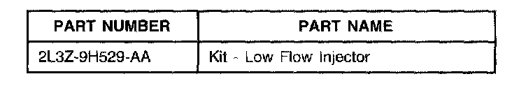
Parts Block
OTHER APPLICABLE ARTICLES: 03-10-4, 02-10-4
SUPERSEDES: 02-10-5
WARRANTY STATUS: INFORMATION ONLY
OASIS CODES: 206000, 601300, 602300, 603300, 607000, 607400, 608000, 609000, 609400, 611000, 611500

Disclaimer