Main Climate Control
Air ConditioningComponent Locations:

Component Locations
Refrigeration System Components - 5.4L And 6.8L (7.3L Diesel Similar):

Refrigeration System Components - 5.4L And 6.8L (7.3L Diesel Similar)
Refrigeration System Components - Motorhome Chassis:

Refrigeration System Components - Motorhome Chassis
The A/C refrigerant system is a clutch cycling orifice tube type. The system components are:
^ A/C compressor.
^ A/C clutch.
^ A/C condenser core.
^ A/C evaporator core.
^ Suction accumulator/drier.
^ Connecting refrigerant lines.
The refrigeration system operation is controlled by the following:
^ A/C evaporator core orifice.
^ A/C cycling switch.
^ A/C pressure cut-off switch.
The refrigerant system incorporates an A/C compressor controlled by an A/C cycling switch. The A/C cycling switch senses pressure in the suction accumulator/drier to control operation of the A/C compressor.
An A/C compressor pressure relief valve is installed in the A/C manifold and tube to protect the compressor against excessively high refrigerant pressures. An A/C evaporator core orifice is installed to the condenser to evaporator tube to meter the liquid refrigerant into the A/C evaporator core.
A/C compressor and Clutch Assembly:

A/C compressor and Clutch Assembly
NOTE:
^ Internal A/C compressor components are not serviced separately. The FS-10 A/C compressor is serviced only as an assembly. The A/C clutch, A/C clutch pulley, A/C clutch field coil and the shaft seal are serviceable.
^ Whenever the A/C compressor is replaced due to a failure that produces debris in the system, also replace the suction accumulator/drier and the A/C evaporator core orifice.
The FS-10 A/C compressor has the following characteristics:
^ A ten-cylinder swashplate design utilizing the tangential design mount.
Displacement of 170 cc (10.4 cubic inch).
^ A one-piece lip-type seal (replaceable from the front of the A/C compressor) is used to seal it at the shaft opening in the assembly.
^ Five double-acting pistons operate within the cylinder assembly. The pistons are actuated by a swashplate that changes the rotating action of the shaft to a reciprocating force.
^ Reed-type discharge valves are located between the cylinder assembly and the head at each end of the A/C compressor.
^ The A/C compressor uses PAG Refrigerant Compressor Oil (R-134a Systems) F7AZ-19589-DA (Motorcraft YN-12-C) or equivalent meeting Ford specification WSH-M1C231-B. This oil contains special additives required for the A/C compressor.
Compressor Clutch Components:

The magnetic A/C clutch has the following characteristics:
^ It drives the compressor shaft.
^ When battery positive voltage (B+) is applied to the A/C clutch field coil, the clutch plate and hub assembly is drawn toward the A/C clutch pulley.
^ The magnetic force locks the clutch plate and hub assembly and the A/C clutch together as one unit, causing the compressor shaft to rotate.
^ When B+ is removed from the A/C clutch field coil, springs in the clutch plate and hub assembly move the clutch plate away from the A/C clutch pulley.
A/C Compressor Pressure relief valve:

A/C Compressor Pressure relief valve
An A/C compressor pressure relief valve is incorporated in the compressor A/C manifold and tube to:
^ relieve unusually high refrigerant system discharge pressure buildups, (3103 kPa [450 psi] and above).
prevent damage to the A/C compressor and other system components.
^ avoid total refrigerant loss by closing after the excessive pressure has been relieved.
A/C condenser Core:

A/C condenser Core
The A/C condenser core has the following characteristics:
^ It is an aluminum fin and tube design heat exchanger located in front of vehicle radiator.
^ It cools compressed refrigerant gas by allowing air to pass over fins and tubes to extract heat and by condensing gas to liquid refrigerant as it is cooled.
Refrigerant Lines
The A/C manifold and tube is attached to the A/C compressor with the O-ring seals and has the following features:
^ The upstream side contains low pressure refrigerant gas.
^ The downstream side contains high pressure refrigerant gas.
^ A serviceable high pressure A/C charge port valve is located on the downstream side.
^ The downstream side also contains a fitting used to mount the A/C pressure cut-off switch. A long-travel Schrader-type valve stem core is installed in the fitting so that the A/C pressure cut-off switch can be removed without discharging the A/C system.
A/C Evaporator Core:

A/C Evaporator Core
The A/C evaporator core is the plate/fin type with a unique refrigerant flow path.
^ A mixture of refrigerant and oil enters the top of the A/C evaporator core through the A/C evaporator core inlet tube and is routed so it flows through the partitioned first four plate/fin sections.
^ The next four plate/fin sections are partitioned to force the refrigerant to flow toward the top of the A/C evaporator core.
^ Refrigerant repeats the cycle for two more plate/fin sections and then moves out of the A/C evaporator core through the A/C evaporator core outlet tube.
^ This W-pass flow pattern accelerates the flow of the refrigerant and the oil through the A/C evaporator core.
A/C Evaporator Core Orifice:

A/C Evaporator Core Orifice
NOTE: The A/C evaporator core orifice should be replaced only following A/C compressor failures that produce debris in the system.
The A/C evaporator core orifice has the following characteristics:
^ Is located in the A/C evaporator core inlet lube.
^ Has filter screens located on the inlet and outlet ends of the tube body.
^ The inlet filter screen acts as a strainer for the liquid refrigerant flowing through the A/C evaporator core orifice.
^ O-rings on the A/C evaporator core orifice prevent the high-pressure liquid refrigerant from bypassing the A/C evaporator core orifice.
^ Adjustment or service cannot be made to the A/C evaporator core orifice assembly. It must be replaced as a unit.
Suction Accumulator/Drier
NOTE: Replacement of the suction accumulator/drier is necessary only following A/C compressor failures that produce debris in the system.
In addition to the preceding condition, the suction accumulator/drier should also be replaced if one of the following conditions exist:
^ The suction accumulator/drier is perforated.
^ The refrigerant system has been opened to the atmosphere for a period of time longer than required to make a minor repair.
^ There is evidence of moisture in the system such as internal corrosion of metal refrigerant lines or the refrigerant oil is thick and dark.
The suction accumulator/drier is mounted to the A/C accumulator bracket to the right of the vehicle centerline. The inlet tube of the suction accumulator/drier attaches directly to the A/C evaporator core outlet tube and the outlet tube of the suction accumulator/drier attaches to the A/C manifold and tube.
After entering the inlet of the suction accumulator/drier, heavier oil-laden refrigerant contacts an internally mounted dome (which serves as an umbrella) and drips down onto the bottom of the canister.
^ A small diameter oil bleed hole, in the bottom of the vapor return tube, allows the accumulated heavier liquid refrigerant and oil mixture to re-enter the compressor suction line at a controlled rate.
^ As the heavier mixture passes through the small diameter liquid bleed hole, it has a second chance to vaporize and recirculate through the A/C compressor without causing compressor damage due to slugging.
^ A fine mesh screened filter fits tightly around the bottom of the vapor return tube to filter out refrigerant system contaminant particles.
^ A desiccant bag is mounted inside the canister to absorb any moisture which may be in the refrigerant system.
^ A fitting located on the suction accumulator/drier is used to attach the A/C cycling switch. A long-travel Schrader-type valve stem core is installed in the fitting so that the A/C cycling switch can be removed without discharging the A/C system.
A/C Cycling Switch:

A/C Cycling Switch
The A/C cycling switch is mounted on a Schrader valve-type fitting on the side of the suction accumulator/drier.
^ A valve depressor, located inside the threaded end of the A/C cycling switch, presses in on the Schrader valve stem.
^ This allows the suction pressure inside the suction accumulator/drier to control the operation of the A/C cycling switch.
^ The electrical switch contacts open when the suction pressure drops to 152-166 kPa (21-24 psi).
NOTE: A/C cycling pressure switch readings during clutch disengagement (clutch off) may read as high as 186 kPa (27 psi) for a properly operating switch with a normal calibration of 152-166 kPa (21-24 psi)during clutch disengagement. This may be caused by the pressure reading being taken from a low side service charge port that is not adjacent (within 177.8 mm/7.0 inches) of the A/C cycling switch. A pressure drop in the A/C line results in high readings.
^ The contacts close when the suction pressure rises to 269-317 kPa (38-46 psi).
^ When the A/C cycling switch contacts close, the A/C clutch field coil is energized.
^ When the A/C cycling switch contacts open, the A/C clutch field coil is deenergized and compressor operation stops.
^ The A/C cycling switch will control the A/C evaporator core pressure at a point where the plate/fin surface temperature will be maintained slightly above freezing.
^ This prevents icing of the A/C evaporator core and blockage of airflow.
^ It is not necessary to discharge the refrigerant system to remove the A/C cycling switch.
A/C Pressure Cut-Off Switch:

A/C Pressure Cut-Off Switch
The A/C pressure cut-off switch is used to interrupt the A/C compressor operation in the event of high system discharge pressures.
^ The A/C pressure cut-off switch is mounted on a Schrader valve-type fitting on the high pressure side of the A/C manifold and tube.
^ A valve depressor, located inside the threaded end of the A/C pressure cut-off switch, presses on the Schrader valve stem.
^ This allows the A/C pressure cut-off switch to monitor the compressor discharge pressure.
^ When the compressor discharge pressure rises to approximately 3103 kPa (450 psi), the switch contacts open, disengaging the A/C compressor.
^ When the pressure drops to approximately 1793 kPa (260 psi), the contacts close to allow operation of the A/C compressor.
^ It is not necessary to discharge the refrigerant system to remove the A/C pressure cut-off switch.
Spring Lock Coupling:
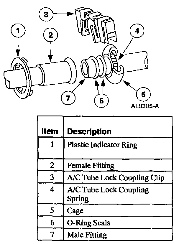
Spring Lock Coupling
The spring lock coupling is a refrigerant line coupling held together by a garter spring inside a circular cage.
^ When the coupling is connected together, the flared end of the female fitting slips behind the garter spring inside the cage of the male fitting.
^ The garter spring and cage then prevent the flared end of the female fitting from pulling out of the cage.
^ Three O-ring seals are used to seal between the two halves of the A/C condenser core couplings, all other couplings have two O-ring seals.
^ These O-ring seals are green in color and are made of special material.
^ Use only the green O-ring seals listed in the Ford Master Parts Catalog for the spring lock coupling.
^ A p1astic indicator ring is used on the spring lock couplings of the A/C evaporator core to indicate, during vehicle assembly, that the coupling is connected. Once the coupling is connected, the indicator ring is no longer necessary but will remain captive by the coupling near the cage opening.
^ The indicator ring may also be used during service operations to indicate connection of the coupling.
^ An A/C tube lock coupling clip may be used to secure the coupling but is not required.
Service Gauge Port Valve:

Service Gauge Port Valve
The high-pressure service gauge port valve is located on the A/C manifold and tube.
The low pressure service gauge port valve is located on the suction accumulator/drier.
The fitting is an integral part of the refrigeration line or component.
^ Special couplings are required for both the high side and the low side service gauge ports.
^ The Schrader-type valve core can be replaced if the seal leaks.
^ Always install the A/C charging valve cap on the service gauge port valves after repairing the refrigerant system.