Drive Pinion
Drive PinionSpecial Tools:

Special Tools:

Special Tool(s)
Removal
1. Remove the differential case.
2. Mark the driveshaft flange and the pinion flange for correct alignment during installation.

3. Remove the four bolts.

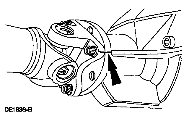
4. CAUTION: The driveshaft centering socket yoke fits tightly on the rear axle pinion flange pilot. Never hammer on the driveshaft or any of its components to disconnect the yoke from the flange. Pry only in the area shown with a suitable tool to disconnect the yoke from the flange.
Using a suitable tool as shown, disconnect the driveshaft centering socket yoke from the rear axle pinion flange. Position the driveshaft out of the way.

5. Install a Nm (inch-pound) torque wrench on the pinion nut and record the torque required to maintain rotation of the pinion through several revolutions.
6. Remove the pinion flange and pinion nut.

7. Using a soft-faced hammer and the special tool, drive the pinion assembly out of the front bearing cone and remove it through the rear of the housing.
^ Remove the rear axle drive pinion seal.
^ Remove the rear axle drive pinion shaft oil slinger.

8. NOTE: Remove the collapsible spacer and discard it.
Using the special tool, remove the pinion bearing.

9. NOTE: Do not remove the pinion bearing cups from the housing unless the cups are damaged.
Using the special tools, remove the outer differential bearing cup.

10. Using the special tools, remove the inner differential bearing cup.
Installation

1. NOTE: This step and the following step show the preferred method for installing the pinion bearing cups. An alternate method is shown following these two steps.
Position the special tools and the inner and outer bearing cups in their respective bores.
1 After placing the inner and outer bearing cups in their bores, place the special tool (inner) on the inner pinion bearing cup.
2 Place the special tool (outer) on the outer pinion bearing cup.
3 Install the special tool.

2. Tighten the special tool to seat the pinion bearing cups into their bores.

3. NOTE: This step and the following step are alternate methods for installing the pinion bearing cups. Carry out these two steps if pinion bearing cup installation was not done in the previous steps.
Using the special tools, drive the outer pinion bearing cup into the rear axle housing.

4. Using the special tools, drive the inner pinion bearing cup into the axle housing.

5. CAUTION: Whenever new cups are installed, new pinion bearings must also be installed.
NOTE: If a feeler gauge can be inserted between a cup and the bottom of its bore at any point around the cup, the cup is not correctly seated.
Make sure the cups are correctly seated in their bores.


6. NOTE: Apply only a light oil film on the pinion bearings before assembling the tool.
Assemble and position the special tools.

7. NOTE: This step duplicates final pinion bearing preload.
Tighten the special tool to the specification shown.

8. NOTE: The special tool must be offset to obtain an accurate reading.
Rotate the special tool several half-turns to make sure of correct seating of the pinion bearings and position the special tool.

9. Install the special tool.
1 Position the special tool.
2 Install the differential side bearing caps.
3 Install the four differential side bearing cap bolts.

10. NOTE: Drive pinion bearing adjustment shims must be flat and clean.
NOTE: A slight drag should be felt for correct shim selection. Do not attempt to force the pinion shim between the Gauge Block and the Gauge Tube. This will minimize selection of a pinion shim thicker than required, which results in a deep tooth contact in final assembly of integral rear axle assemblies.
Use a drive pinion bearing adjustment shim as a gauge for shim selection.
^ After the correct shim thickness has been determined, remove the special tool.

11. Using the special tools, press the pinion bearing and pinion shim until seated firmly on the pinion.

12. Place a new drive pinion collapsible spacer on the pinion shaft against the pinion stem shoulder.

13. CAUTION: Installation without the correct tool can result in early seal failure. If the rear axle drive pinion seal becomes cocked during installation, remove it and install a new one.
Install a new rear axle drive pinion seal.
1 Install the front pinion bearing cone and roller.
2 Install the rear axle drive pinion shaft oil slinger in the rear axle housing.
3 Install the rear axle drive pinion seal on the special tool.

14. NOTE: Coat the lips of the rear axle drive pinion seal with Premium Long-Life Grease XG-1-C or equivalent meeting Ford specification ESA-M1C75-B.
Place the special tool in the rear axle drive pinion seal bore, and drive the rear axle drive pinion seal into place.

15. From inside the rear axle housing, install the drive pinion assembly (drive pinion, shims, rear bearing cone and roller, and drive pinion collapsible spacer) into the rear axle bore.
16. Lubricate the pinion flange splines.
^ Use SAE 75W-140 High Performance Rear Axle Lubricant F1TZ-19580-B or equivalent meeting Ford specification WSL-M2Cl92-A.

17. NOTE: Disregard the scribe marks if a new pinion flange is being installed.
Align the pinion flange with the drive pinion shaft.

18. With the drive pinion in place in the rear axle housing, install the pinion flange using the special tool.

19. Position the new pinion nut.

20. CAUTION: Under no circumstances is the pinion nut to be backed off to reduce preload. If reduced preload is required, a new collapsible spacer and pinion nut must be installed.
Using the special tool to hold the pinion flange, tighten the pinion nut.
^ Rotate the pinion occasionally to make sure the cone and roller bearings are seating correctly.
^ Install a Nm (inch-pound) torque wrench on the pinion nut.
^ Rotating the pinion through several revolutions, take frequent cone and roller bearing torque preload readings until the original recorded preload reading is obtained.
^ If the original recorded preload is lower than specifications, tighten to the appropriate specifications for used bearings. If the preload is higher than specification, tighten the nut to the original reading as recorded.

21. Position the rear driveshaft and align the marks on the pinion flange.

22. CAUTION: The driveshaft centering socket yoke fits tightly on the rear axle pinion flange pilot. To make sure that the yoke seats squarely on the flange, tighten the bolts evenly in a cross pattern as shown.
Install the bolts and tighten to specification.
23. Install the differential case in the rear axle differential.