Main Shaft
Main ShaftPart 1 Of 3:

Part 2 Of 3:

Part 3 Of 3:

Special Tool(s)
Disassembly

Mainshaft Components-Disassembled View
1. Rotate the mainshaft. Position the mainshaft in the Gear Pack Assembly Fixture with the input shaft pointing upward.

2. NOTE: Installing a new input shaft will affect mainshaft clearance. Carry out a mainshaft clearance measurement.
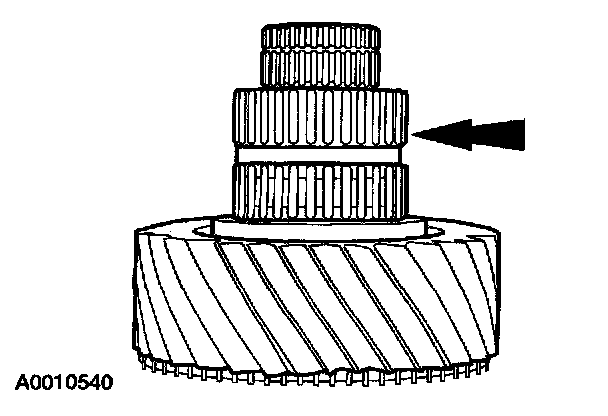
Remove the input shaft.

3. Using the special tools, remove and discard the input shaft bearing.

4. Remove and discard the input shaft rear oil dam.

5. Inspect the input shaft and input shaft bearing for damage or wear.
6. CAUTION: To prevent damage, do not heat the bearing higher than 150°C (300°F).
A new input shaft bearing should be heated in advance of the assembly procedure. Heating components will ease the assembly process. Place the input shaft bearing into the Gear/Bearing Heater. Make sure the bearing is heated to 150°C (300°F).

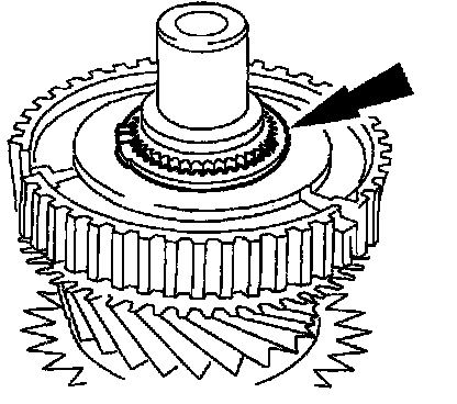
7. Using the special tools, remove the input shaft pocket bearing.
^ Inspect the bearing for wear or damage. Install a new bearing as necessary.

8. Remove and discard the snap ring.

9. Using the special tools, remove the third and fourth synchronizer assembly and third gear.
^ Inspect third gear for wear or damage. Install a new gear as necessary.

10. Disassemble the third and fourth synchronizer assembly.
^ Inspect the components for wear or damage. Install new components as necessary.

11. Check the clearance between the synchronizer ring and the gear.
1 Place the synchronizer ring onto the synchronizer sliding sleeve. Position the synchronizer ring on the gear.
2 Insert a feeler gauge and measure the clearance, while applying pressure and rotating the synchronizer ring. The clearance should be the same around the entire circumference.
^ Place the feeler gauge between the ring and gear clutching teeth. The ring has a raised section, inserting the feeler gauge past the teeth will give an incorrect reading.
^ If the clearance is less than 1.0 mm (0.04 inch), install a new synchronizer assembly.
12. Remove the mainshaft needle bearing.
^ Inspect the bearing for wear or damage. Install a new bearing as necessary.

13. NOTE: When installing the Bearing Puller, make sure it is installed above the mainshaft bearing race.
Using the special tool, press the mainshaft gear bushing off the mainshaft.

14. Using the special tool, press the mainshaft second gear thrust washer, the mainshaft second gear, the mainshaft needle bearing, the mainshaft gear bushing, first and second synchronizer assembly and mainshaft first gear.
^ Inspect the gears and bearing for wear or damage. Install new components as necessary.

15. Remove the mainshaft first gear needle bearing.
^ Inspect the bearing for wear or damage. Install a new bearing as necessary.

16. Using the special tools, remove the mainshaft center bearing.
^ Inspect the bearing for wear or damage. Install a new bearing as necessary.

17. Disassemble the first and second synchronizer assembly.
^ Inspect the components for wear or damage. Install a new synchronizer assembly as necessary.

18. Check the clearance between the synchronizer ring and the gear clutching teeth.
1 Place the synchronizer ring onto the synchronizer sliding sleeve. Position the
synchronizer ring on the gear.
2 Insert a feeler gauge and measure the clearance, while applying pressure and rotating the synchronizer ring. The clearance should be the same around the entire circumference.
^ Place the feeler gauge between the ring and gear clutching teeth. The ring has a raised section, inserting the feeler gauge past the teeth will give a wrong reading.
^ If the clearance is less than 1.0 mm (0.04 inch), install a new synchronizer assembly.
19. CAUTION: To prevent damage, do not heat bearings, thrust washers, bushings or the synchronizer bodies higher than 150°C (300°F),
New or original components should be heated in advance of the assembly procedure. Heating the specified components will ease the assembly process. Place the input shaft pocket bearing, the mainshaft second gear thrust washer, the mainshaft center bearing, the synchronizer bodies and the mainshaft gear bushings into the Gear/Bearing Heater.
Assembly
1. Inspect the mainshaft and all mainshaft components for wear or damage.
2. CAUTION: Do not reassembly the mainshaft dry. Apply lubricant throughout the assembly procedure.
Lubricate all mainshaft components with the recommended transmission lubricant during reassembly.

3. Install the center mainshaft bearing.
^ Make sure the bearing is installed against the stop on the mainshaft.

4. Using the special tool, position the mainshaft on the press with the input end facing upward.
^ Using a hammer and punch, remove the bearing cup from the intermediate housing, then install it on the bearing. This will prevent any damage to the bearing during installation.

5. Install the first gear bearing and the first gear.

6. Install the three synchronizer rings for first gear.
^ Make sure the tabs on the synchronizer ring are in the slots on the gear.
^ Make sure to align the notches on the synchronizer body with the tabs on the synchronizer ring.

7. Using the special tools, press the first and second gear synchronizer body into place.
^ The numbers on the synchronizer hub must face upward.
^ Make sure to align the notches on the synchronizer body with the tabs on the synchronizer ring.

8. NOTE: Install the synchronizer sliding sleeve with the flats aligned with the detent notches.
Install the synchronizer sliding sleeve.
^ The sliding sleeve has three flat areas which need to line up with the detent area of the synchronizer body.

9. Install the synchronizer spring and plate, then tilt the plate up and install the detent ball.
^ If the springs are difficult to install, check the alignment of the synchronizer sliding sleeve flat areas.

10. NOTE: Position the synchronizer into the neutral position.
Install the synchronizer rings for second gear.
^ Align the tabs on the synchronizer rings with the slots in the synchronizer body.

11. Install the mainshaft second gear bushing.

12. NOTE: Let the mainshaft second gear bushing cool down for 2-4 minutes before trying to install the mainshaft needle bearing.
Install the mainshaft needle bearing.

13. Install second gear.
^ Make sure to align the tabs on the synchronizer ring with the slots on the gear.

14. Using the special tools. press the mainshaft second gear thrust washer into place.

15. Using the special tool, install the mainshaft third gear bushing on the mainshaft.
^ Pull the first/second gear sliding sleeve into the neutral position.

16. NOTE: Let the mainshaft third gear bushing cool down for 2-4 minutes before trying to install the mainshaft needle bearing.
Install the mainshaft needle bearing.

17. Install the mainshaft third gear and synchronizer ring.

18. Install the third and fourth gear synchronizer body.
^ The numbers on the synchronizer body must face upward.
^ Make sure to align the synchronizer body notches with the tabs on the synchronizer ring.
19. Install a new snap ring.
^ Install the snap ring with the small holes facing upward.
^ The snap ring is a selective fit. The correct snap ring should completely fill the groove when seated.

20. CAUTION: Press the input shaft pocket bearing onto the mainshaft by the inner race only. Pressing on the outer race will damage the bearing.
Press the input shaft pocket bearing into place.
^ Make sure the bearing is correctly seated. At the bottom of the bearing, there should be no gap. At the top of the bearing, check for a small amount of the mainshaft to be above the inner bearing race.
21. Remove the mainshaft from the press and reinstall it in the Gear Pack Assembly Fixture.

22. Install and position the synchronizer sliding sleeve down on the synchronizer body, install the springs and detents.

23. Install the synchronizer ring, linen move the synchronizer sliding sleeve up on the synchronizer body.

24. CAUTION: Do not drive against the bearing cone. Drive against the inner race only.
Using a suitable driver, install a new input shaft bearing.
^ Seat the bearing against its stop.

25. Using the special tool, install the input shaft rear oil dam.
^ Rotate the input shaft to make sure the input shaft rear oil dam is completely seated.

26. Install the input shaft.
^ Fill the input shaft pocket with a suitable engine assembly white grease.

27. NOTE: If the following axial gear clearances are not within specification, it will be necessary to disassemble and reinspect.
Using the special tool, check the axial gear clearance at the mainshaft first gear.

28. Using the special tool, check the axial gear clearance at the mainshaft second pear.
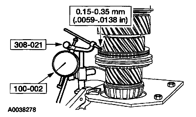
29. Rotate the mainshaft with the input shaft facing downward. Using the special tool, check the axial gear clearance at the mainshaft third gear.