Attachment III - Certain 2004 MY E-Series Vehicles

OVERVIEW
The 2004 model year program involves replacing the exhaust pressure (EP) sensor and connector and recalibrating the powertrain control module (PCM), transmission control module (1CM) and the fuel injection control module (FICM) with the latest software.
EP SENSOR AND CONNECTOR REPLACEMENT
NOTE:
All splices are to be made using tools provided in the Rotunda Wire Splice Tool Kit 164-R5903.
The repair kit contains the connector and pigtails, butt splice connectors and heat shrink tubing.
The EP sensor is located on a bracket above the left valve cover in front of the glow plug relay.

See Figure 1.
1. Remove the engine cover from inside the passenger compartment.
2. Disconnect the EP sensor.
3. While holding the tube nut remove the EP sensor.
4. Install the new EP sensor and tighten to 10 Nm (89 lb-in).
5. Remove the tape from the vehicle harness back to the original take-out location.
6. CAUTION: The replacement connector has only one color wire, so location identification is crucial for a proper repair.
Label the wires identifying the cavity in which they are located. Place identifying tags at least a few inches away from the connector to be cut off.

7. Cut the wires about 25 mm (1 inch) behind the connector on the vehicle harness MAKING SURE TO LEAVE THE IDENTIFYING TAGS ON THE HARNESS and discard the old connector. See Figure 2.
8. Strip about 7 mm (1/4 inch) of insulation from the wires on the new pigtail.
9. Using the crimp tool provided in the Rotunda Tool Kit, install the buff splice connectors provided in the service kit onto the replacement connector pigtail.
10. Strip about 7 mm (1/4 inch) of insulation from the wires on the vehicle harness.
11. Position the heat shrink over the wires on the new connector.
12. Matching the wires on the pigtail to the identifying tags on the vehicle harness, crimp the new butt splice connectors to the vehicle harness. Lightly tug on the wires to make sure of quality connections.
13. Position the heat shrink tubing over the butt splice connectors, then using the provided Flameless Heat Gun and deflector, heat the tubes on the vehicle harness until they shrink and adhesive flows from the ends, indicating a water-tight seal.
14. Fold the repaired harness to mirror the original harness length and tape the harness.
15. Install a length of convolute over the spliced section of harness and secure with tape.
16. Apply electrical grease to the face of the connector, forcing a small amount into all three (3) terminals.
17. Connect the EP harness connector.
18. Install the engine cover.
19. Proceed to Module Recalibration in this Attachment III.
MODULE RECALIBRATION
NOTE:
This recalibration, using WDS software Version B40.7 or higher, or B41.1 or higher, will update the PCM, TCM and FICM. This new calibration is not included in the B41 CD. Calibration files may also be obtained at the website.
1. Connect a battery charger to the vehicle.
2. Using Worldwide Diagnostic System (WDS), recalibrate the modules to the latest level calibration.
3. VERIFY THE WDS IS LOADED WITH SOFTWARE VERSION B40.7 OR HIGHER, ORB41.1 OR HIGHER.
4. Select Module Configuration Programming (MCP) and follow the WDS display instructions.
^ If unable to recalibrate the modules:
- module replacement will not be covered under this program.
- prior to disconnecting the WDS from the vehicle and closing the session, call the Special Service Support Center.
5. Perform a self-test to verify there are no further concerns.
6. Proceed to Road Test Procedure in this Attachment III.
ROAD TEST PROCEDURE
Check OASIS to verify there are no other Field Service Actions applicable to this vehicle prior to performing the Road Test Procedure.
Test drive the vehicle to make sure no drivability concerns exist prior to returning the vehicle to the owner.
NOTE:
To address any customer concerns for vehicles that are out of warranty and exhibit engine performance issues after the road test, please follow the guidelines in the Warranty and Policy Manual.
AUTHORIZED MODIFICATIONS LABEL INSTALLATION
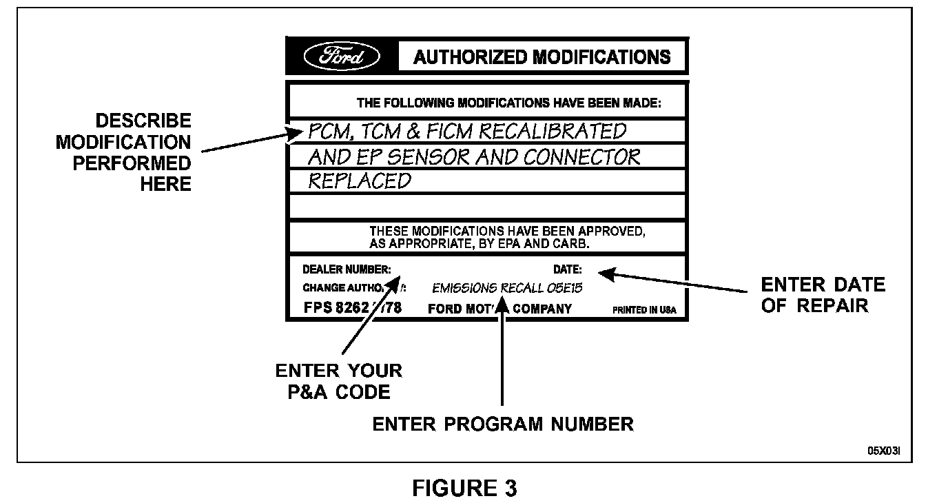
1. Obtain and prepare the Authorized Modifications Label. Describe the modification performed, and enter your P&A Code, date of repair and the program type and program number. See Figure 3.
PROOF OF CORRECTION CERTIFICATE

1. Provide the owners of vehicles registered in California and Massachusetts with a completed "Vehicle Emissions Recall - Proof of Correction" certificate. See Figure 4.