Part 1
EngineSpecial Tool(s):

Special Tool(s):

Material:

Material:

Engine - Upper End (Part 1):

Engine - Upper End (Part 2):

Engine - Upper End (Part 3):

Engine - Front end (Part 1):

Engine - Front end (Part 2):

Engine - Lower end (Part 1):

Engine - Lower end (Part 2):

Engine - Lower end (Part 3):

Assembly
1. Record the main bearing code found on the front of the engine block.

2. Record the main bearing code found on the back of the crankshaft.

3. Using the data recorded earlier and the Bearing Select Fit Chart, Standard Bearings, determine the required bearing grade for each main bearing.
^ Read the first letter of the engine block main bearing code and the first letter of the crankshaft main bearing code.
^ Read down the column below the engine block main bearing code letter, and across the row next to the crankshaft main bearing code letter, until the 2 intersect. This is the required bearing grade for the No. 1 crankshaft main bearing.
^ As an example, if the engine block code letter is "F" and the crankshaft code letter is "D", the correct bearing grade for this main bearing is a "2".
^ Repeat this process for the remaining 4 main bearings.

4. If oversize bearings are being used, use the procedure in the previous step and the Bearing Select Fit Chart, Oversize Bearings to determine the required bearing grade for each main bearing.

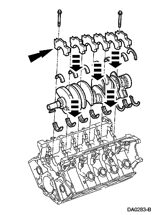
5. NOTE: Before assembling the cylinder block, all sealing surfaces must be free of chips, dirt, paint and foreign material. Also, make sure the coolant and oil passages are clear.
Install the crankshaft upper main bearings into the cylinder block and lubricate them with clean engine oil.
6. NOTE: Before assembling the cylinder block, all sealing surfaces must be free of chips, dirt, paint and foreign material. Also, make sure the coolant and oil passages are clear.
Install the crankshaft upper main bearings into the cylinder block and lubricate them with clean engine oil.

7. Install the crankshaft into the cylinder block and onto the upper crankshaft main bearings.

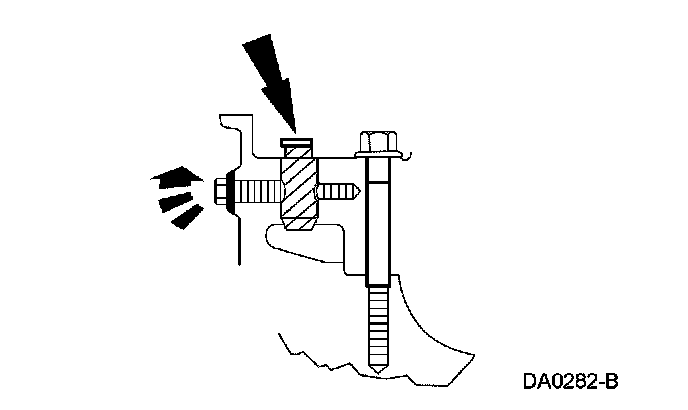
8. NOTE: If equipped, the oil groove on the thrust washer must face toward the front of the engine (against the crankshaft surface).
Push the crankshaft rearward and install the rear upper crankshaft thrust washer at the back of the No. 6 main boss.

9. NOTE: If equipped, the oil groove on the thrust washer must face toward the front of the engine (against the crankshaft surface).
Push the crankshaft forward and install the front upper crankshaft thrust washer at the front of the No. 6 main boss.

10. NOTE: To aid in assembly, apply petroleum jelly to the back of the crankshaft thrust washer.
NOTE: If equipped, the oil groove on the thrust washer must face toward the front of the engine (against the crankshaft surface).
Install the lower crankshaft thrust washer to the back side of the No. 6 main bearing cap, with oil grooves facing the crankshaft surface, and install the No. 6 rear main bearing cap.

11. Install the No. 1 through No. 5 crankshaft lower main bearings into the main bearing caps. Locate the main bearing caps on the cylinder block and, keeping the cap as square as possible, alternately draw the cap down evenly using the cap fasteners.
12. Install the bolts.
13. Install the 10 dowel pins so that the flat sides face the crankshaft. Install the cross-mounted bolts.
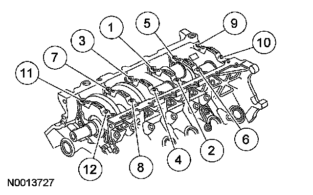
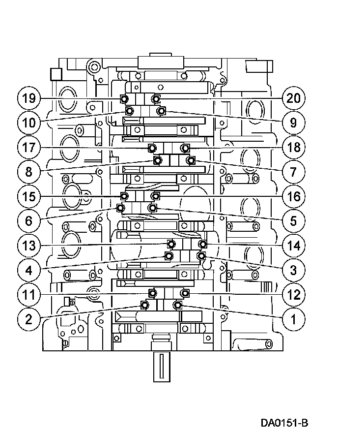
14. Tighten fasteners 1 through 12 in 2 stages, in the sequence shown.
^ Stage 1: Tighten to 40 Nm (30 ft. lbs.).
^ Stage 2: Tighten an additional 90 degrees.
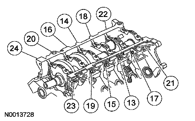
15. Tighten fasteners 13 through 24 in 2 stages, in the sequence shown.
^ Stage 1: Tighten to 30 Nm (22 ft. lbs.).
^ Stage 2: Tighten an additional 90 degrees.
16. Check the piston-to-cylinder block and piston ring clearances.
17. Assemble the 10 pistons.
18. Make sure the ring gaps (oil spacer-A, oil ring-B, compression ring-C) are correctly spaced around the circumference of the piston.

19. Using the special tools, install the piston and connecting rod assembly.

20. CAUTION: Do not scratch the cylinder walls or crankshaft journals with the connecting rod.
Once the connecting rod is seated on the crankshaft journal, remove the special tools.

21. CAUTION: The rod cap installation must keep the same orientation as marked during disassembly.
NOTE: The connecting rod caps are of the "cracked" design and must mate with the connecting rod ends. Excessive bearing clearance will result if not mated correctly.
Install the connecting rod bearings, position the connecting rod cap and loosely install the 2 new bolts.
22. NOTE: Be sure to tighten the bolts in 2 stages.
Tighten the connecting rod bolts in the sequence shown.
^ Stage 1: Tighten to 43 Nm (32 ft. lbs.).
^ Stage 2: Tighten an additional 105 degrees.
23. Rotate the crankshaft and repeat the procedure to position each connecting rod at bottom dead center until all bolts are tightened to specification.
24. Position the oil pump and install the bolts.
^ Tighten to 10 Nm (89 inch lbs.).

25. Install the oil pump screen and pickup tube spacer.
^ Tighten to 25 Nm (18 ft. lbs.).

26. CAUTION: Make sure the O-ring is in place and not damaged. A missing or damaged O-ring can cause foam in the lubrication system, low oil pressure and severe engine damage.
NOTE: Clean and inspect the mating surfaces and install a new O-ring. Lubricate the O-ring with clean engine oil prior to installation.
Position the oil pump screen and pickup tube and install the bolts.
^ Tighten the oil pump screen and pickup tube-to-oil pump bolts to 10 Nm (89 inch lbs.).
^ Tighten the oil pump screen and pickup tube-to-spacer bolt to 25 Nm (18 ft. lbs.).

27. Rotate the crankshaft to position the keyway at 12 o'clock.

28. CAUTION: Make sure all coolant residue and foreign material are cleaned from the block surface and cylinder bore.
CAUTION: The use of sealing aids (aviation cement, copper spray and glue) is not permitted. The gasket must be installed dry.
CAUTION: The cylinder head bolts must be discarded and new bolts installed. They are tighten-to-yield designed and cannot be reused.
NOTE: Do not turn the crankshaft until instructed to do so.
NOTE: LH shown, RH similar.
Using the special tools, position the cylinder head gaskets and cylinder heads over the dowels and install the cylinder head bolts loosely.

29. NOTE: Be sure to tighten the bolts in 3 stages.
Tighten the bolts in the sequence shown.
^ Stage 1: Tighten to 40 Nm (30 ft. lbs.).
^ Stage 2: Tighten an additional 90 degrees.
^ Stage 3: Tighten an additional 90 degrees.

30. Remove the special tool from the LH cylinder head.

31. Remove the special tool from the RH cylinder head.

32. Install the hydraulic lash adjusters into the RH and LH cylinder heads.
^ Lubricate the hydraulic lash adjusters with clean engine oil prior to installation.

33. CAUTION: If the components are to be reinstalled, they must be installed into their original locations.
NOTE: Camshaft shown installed to clarify camshaft roller follower position.
NOTE: Lubricate the camshaft roller followers with clean engine oil prior to installation.
Install only the identified camshaft roller followers onto the RH cylinder head.

34. CAUTION: If the components are to be reinstalled, they must be installed into their original locations.
NOTE: Camshaft shown installed to clarify camshaft roller follower position.
NOTE: Lubricate the camshaft roller followers with clean engine oil prior to installation.
Install only the identified camshaft roller followers onto the LH cylinder head.

35. Install the LH and RH camshafts.
^ Lubricate the camshaft and camshaft journals with clean engine oil prior to installation.
36. Install the LH and RH camshaft bearing caps in their original locations.
^ Lubricate the camshaft bearing caps with clean engine oil.
^ Position the front camshaft bearing cap.
^ Position the remaining camshaft bearing caps.
^ Install the bolts loosely.
37. Tighten the LH camshaft bearing cap bolts in 2 stages:
^ Stage 1: Tighten to 8 Nm (71 inch lbs.) in the sequence shown.
^ Stage 2: Tighten an additional 45 degrees.

38. Tighten the RH camshaft bearing cap bolts in 2 stages:
^ Stage 1: Tighten to 8 Nm (71 inch lbs.) in the sequence shown.
^ Stage 2: Tighten an additional 45 degrees.

39. Install the balance shaft drive gear onto the LH camshaft.
40. Install both camshaft sprockets and camshaft sprocket bolts finger tight.