Pinpoint Test L: Temperature Control is Inoperative/Does Not Operate Correctly - EMTC Systems, Vehicles Not Equipped With Elect
Climate Control System
Pinpoint Tests
Pinpoint Test L: Temperature Control is Inoperative/Does Not Operate Correctly - EMTC Systems, Vehicles Not Equipped With Electric Heater
Refer to Wiring Diagram Set 54, Manual Climate Control System for schematic and connector information. Diagrams By Number
Normal Operation
Under normal operation, to rotate the temperature blend door actuator, the HVAC module supplies voltage and ground to the temperature blend door actuators through the door actuator motor circuits. To reverse the temperature blend door actuator rotation, the HVAC module reverses the voltage and ground circuits.
The temperature blend door actuator feedback resistors are supplied a ground from the HVAC module by the temperature blend door actuator return circuits and a 5-volt reference voltage on the temperature blend door actuator reference circuits. The HVAC module reads the voltage on the temperature blend door actuator feedback circuits to determine the temperature blend door actuator position by the position of the actuator feedback resistor wiper arm.
During an actuator calibration cycle, the HVAC module drives the temperature blend door until the door reaches both internal stops in the HVAC case. If the temperature blend door is temporarily obstructed or binding during a calibration cycle, the HVAC module may interpret this as the actual end of travel for the door. When this condition occurs and the HVAC module commands the actuator to its end of travel, the airflow may not be from the expected outlets.
- DTC B2266 (Left Side Blend Door Circuit Failure) - The module senses no change in actuator feedback voltage when the actuator motor has been energized.
This pinpoint test is intended to diagnose the following:
- Wiring, terminals or connectors
- Blend door actuator
- HVAC module - Electronic Manual Temperature Control (EMTC)
- Stuck or bound linkage or door
PINPOINT TEST L: TEMPERATURE CONTROL IS INOPERATIVE/DOES NOT OPERATE CORRECTLY - EMTC SYSTEMS, VEHICLES NOT EQUIPPED WITH ELECTRIC HEATER
-------------------------------------------------
L1 CHECK THE FEEDBACK POTENTIOMETER TOTAL RESISTANCE
- Disconnect: HVAC Module - EMTC C2357A.
- Measure the resistance between HVAC module - EMTC C2357A-11, circuit LH111 (BN/WH), harness side and HVAC module - EMTC C2357A-10, circuit RH111 (GY/BU), harness side.

- Is the resistance greater than 500 ohms?
Yes
GO to L3.
No
GO to L2.
-------------------------------------------------
L2 CHECK CIRCUITS RH111 (GY/BU) AND LH111 (BN/WH) FOR A SHORT TOGETHER
NOTE: Access to the connector in the following step is difficult. Before performing this step, visually inspect the actuator and its harness for obvious damage. If no damage is evident, proceed with the test.
- Disconnect: Defrost/Panel/Floor Door Actuator C2248.
- Measure the resistance between HVAC module - EMTC C2357A-11, circuit LH111 (BN/WH), harness side and HVAC module - EMTC C2357A-10, circuit RH111 (GY/BU), harness side.
- Is the resistance greater than 500 ohms?
Yes
INSTALL a new defrost/panel/floor door actuator. CONNECT the actuator electrical connector before the HVAC module electrical connector(s). This will allow the new actuator to be calibrated when the HVAC module is reconnected. TEST the system for normal operation.
No
CARRY OUT the Temperature Blend Door Actuator Component Test on the LH blend door actuator. If the actuator tests OK, REPAIR circuits LH111 (BN/WH) and RH111 (GY/BU) for a short together. If a new actuator is installed, CONNECT the actuator electrical connector before the HVAC module electrical connector(s). This will allow the new actuator to be calibrated when the HVAC module is reconnected. CLEAR the DTCs. REPEAT the self-test. TEST the system for normal operation. Temperature Blend Door Actuator
-------------------------------------------------
L3 CHECK THE POTENTIOMETER LOW- AND HIGH-SIDE RESISTANCE
- Measure the low-side resistance between HVAC module - EMTC C2357A-10, circuit RH111 (GY/BU), harness side and HVAC module - EMTC C2357A-7, circuit VH439 (GY/VT), harness side.

- Measure the high-side resistance between HVAC module - EMTC C2357A-11, circuit LH111 (BN/WH), harness side and HVAC module - EMTC C2357A-7, circuit VH439 (GY/VT), harness side.

- Are the resistances between 187 and 6,563 ohms?
Yes
GO to L4.
No
CARRY OUT the Temperature Blend Door Actuator Component Test. If a new actuator is installed, CONNECT the actuator electrical connector before the HVAC module connector(s). This will allow the new actuator to be calibrated when the HVAC module is reconnected. If the actuator tests OK and: Temperature Blend Door Actuator
If the low-side resistance only is greater than 6,563 ohms, REPAIR circuit RH111 (GY/BU) for an open. CLEAR the DTCs. REPEAT the self-test. TEST the system for normal operation.
If the low-side resistance only is less than 187 ohms, REPAIR circuit VH439 (GY/VT) for a short to circuit RH111 (GY/BU). CLEAR the DTCs. REPEAT the self-test. TEST the system for normal operation.
If the high-side resistance only is greater than 6,563 ohms, REPAIR circuit LH111 (BN/WH) for an open. CLEAR the DTCs. REPEAT the self-test. TEST the system for normal operation.
If the high-side resistance only is less than 187 ohms, REPAIR circuit VH439 (GY/VT) for a short to circuit LH111 (BN/WH). CLEAR the DTCs. REPEAT the self-test. TEST the system for normal operation.
If both the high-side and low-side resistance is greater than 6,563 ohms, REPAIR circuit VH439 (GY/VT) for an open. CLEAR the DTCs. REPEAT the self-test. TEST the system for normal operation.
-------------------------------------------------
L4 CHECK CIRCUIT RH111 (GY/BU) OR VH439 (GY/VT) FOR A SHORT TO POWER
- Ignition ON.
- Measure the voltage between ground and the following:
- HVAC module - EMTC C2357A-10, circuit RH111 (GY/BU), harness side.
- HVAC module - EMTC C2357A-7, circuit VH439 (GY/VT), harness side.

- Are any voltages present?
Yes
REPAIR circuit RH111 (GY/BU) or VH439 (GY/VT) for a short to power. CLEAR the DTCs. REPEAT the self-test. TEST the system for normal operation.
No
GO to L5.
-------------------------------------------------
L5 CHECK CIRCUITS LH111 (BN/WH) OR VH439 (GY/VT) FOR A SHORT TO GROUND
- Ignition OFF.
- Measure the resistance between ground and the following:
- HVAC module - EMTC C2357A-11, circuit LH111 (BN/WH), harness side.
- HVAC module - EMTC C2357A-7, circuit VH439 (GY/VT), harness side.
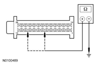
- Are the resistances greater than 10,000 ohms?
Yes
GO to L6.
No
REPAIR circuit LH111 (BN/WH) or VH439 (GY/VT) for a short to ground. CLEAR the DTCs. REPEAT the self-test. TEST the system for normal operation.
-------------------------------------------------
L6 CHECK THE DOOR ACTUATOR OPERATION
NOTE: If a jumper fuse opens while carrying out this test step, repair the circuit(s) for a short.
- With the fused jumper connections made as directed below, measure the resistance between HVAC module - EMTC C2357A-10, circuit RH111 (GY/BU), harness side and HVAC module - EMTC C2357A-7, circuit VH439 (GY/VT), harness side.

- Connect a fused jumper wire between:
- HVAC module - EMTC C2357A-13, circuit SBP15 (WH/RD), harness side and HVAC module - EMTC C2357A-22, circuit CH233 (VT/BN), harness side.
- HVAC module - EMTC C2357A-23, circuit GD133 (BK), harness side and HVAC module - EMTC C2357A-21, circuit CH234 (YE/GN), harness side.
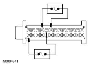
- Remove both the fused jumpers.
- Connect a fused jumper wire between:
- HVAC module - EMTC C2357A-23, circuit GD133 (BK), harness side and HVAC module - EMTC C2357A-22, circuit CH233 (VT/BN), harness side.
- HVAC module - EMTC C2357A-13, circuit SBP15 (WH/RD), harness side and HVAC module - EMTC C2357A-21, circuit CH234 (YE/GN), harness side.

- Does the resistance smoothly increase and/or decrease when the jumpers are connected?
Yes
INSPECT for broken door and linkage. REPAIR as necessary. If no condition is found, GO to L9.
No
GO to L7.
-------------------------------------------------
L7 CHECK THE ACTUATOR MOTOR DRIVE CIRCUITS FOR AN OPEN
NOTE: Access to the connector in the following step is difficult. Before performing this step, visually inspect the actuator and its harness for obvious damage. If no damage is evident, proceed with the test.
- Disconnect: LH Temperature Blend Door Actuator C289.
- Measure the resistance between HVAC module - EMTC C2357A-22, circuit CH233 (VT/BN), harness side and LH blend door actuator C289-6, circuit CH233 (VT/BN), harness side.

- Measure the resistance between HVAC module - EMTC C2357A-21, circuit CH234 (YE/GN), harness side and LH blend door actuator C289-1, circuit CH234 (YE/GN), harness side.

- Are the resistances less than 5 ohms?
Yes
INSPECT for broken door and linkage. REPAIR as necessary. If no condition is found, GO to L8.
No
REPAIR circuit(s) for an open. CLEAR the DTCs. REPEAT the self-test. TEST the system for normal operation.
-------------------------------------------------
L8 CHECK THE ACTUATOR CONNECTION
- Disconnect the actuator connector.
- Check for:
- corrosion.
- pushed-out terminals.
- damaged terminals.
- Connect and correctly seat the actuator connector.
- Clear the DTCs.
- Operate the system and verify the concern is still present.
- Is the concern still present?
Yes
CARRY OUT the Temperature Blend Door Actuator component test. If a new actuator is installed, CONNECT the actuator electrical connector before the HVAC module connector(s). This will allow the new actuator to be calibrated when the HVAC module is reconnected. If the actuator tests OK, GO to L9. Temperature Blend Door Actuator
No
The system is operating correctly at this time. The concern may have been caused by a loose or corroded connector. CLEAR the DTCs. TEST the system for normal operation.
-------------------------------------------------
L9 MODULE ACTUATOR POSITION CALIBRATION
NOTE: The purpose of the module actuator position calibration is to allow the HVAC module to reinitialize and calibrate the actuator stop points. To carry out the calibration, follow the steps below.
- Ignition OFF.
- Inspect the module connectors for:
- corrosion.
- pushed-out terminals.
- damaged terminals.
- Connect and correctly seat all the HVAC module connectors.
- Ignition ON.
- Clear the DTCs.
- Select any position except OFF.
- NOTE: The HVAC module will now initialize and calibrate the actuators. Calibration of the actuators will take approximately 30 seconds.
- Operate the system and verify the concern is still present.
- Is the concern still present?
Yes
INSTALL a new HVAC module. TEST the system for normal operation.
No
The system is now operating correctly at this time. The concern may have been caused by a foreign object in the HVAC case or temporary binding that restricted actuator door travel. CHECK any actuator external linkage. If condition recurs, INSPECT actuator linkage and door for binding and CHECK HVAC case for foreign objects.
-------------------------------------------------