Front Suspension
TOOL REQUIRED- 07MAC-SL00200 Ball Joint remover, 28 mm
- 07JAF-SH20110 Wheel Hub Dis/Assembly Pilot, 38 mm
- 07JAF-SH20120 Wheel Hub Dis/Assembly Shaft, 22.4 x 25.4 mm
- 07749-0010000 Driver
- 07746-0010500 Attachment, 62 x 68 mm
- 07GAF-SE00401 Wheel Hub Dis/Assembly Base
- 07947-6340201 Driver Attachment 58 x 72 mm
- 07965-SD90100 Support Base
- 07GAF-SE00200 Wheel Hub Dis/Assembly Guide Attachment

CAUTION:
- Replace the self-locking nuts after removal.
- The vehicle should be on the ground before any bolts or nuts connected to rubber mounts or bushings are tightened.
- Torque the castle nut to the lower torque specification, then tighten it only far enough to align the slot with the pin hole. Do not align the nut by loosening.
NOTE:
- Use only genuine Honda wheel weights for aluminum wheels. Non-genuine wheel weights may corrode and damage the aluminum wheels.
- On the aluminum wheels, remove the center cap from the inside of the wheel after removing the wheel.
- Before installing the brake disc, clean the mating surfaces of the front wheel hub and brake disc.
- Before installing the wheel, clean the mating surfaces of the brake disc and wheel.
- Wipe off the grease before tightening the nut at the ball joint.
1. Loosen the wheel nuts slightly.
2. Raise the front of vehicle, and support it with safety stands in the proper locations.

3. Remove the wheel nuts and wheel.
4. Raise the locking tab on the spindle nut, then remove the nut.

5. Remove the brake hose mounting bolts.
6. Remove the caliper mounting bolts and hang the caliper assembly to one side.
CAUTION: To prevent accidental damage to the caliper assembly or brake hose, use a short piece of wire to hang the caliper from the undercarriage.
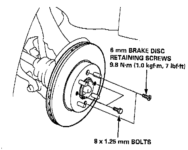
7. Remove the 6 mm brake disc retaining screws.
8. Screw two 8 x 1.25 mm bolts into the disc to push it away from the wheel hub.
NOTE: Turn each bolt two turns at a time to prevent cocking the disc excessively.
9. Remove the brake disc from the knuckle.
10. Check the front wheel hub for damage and cracks.
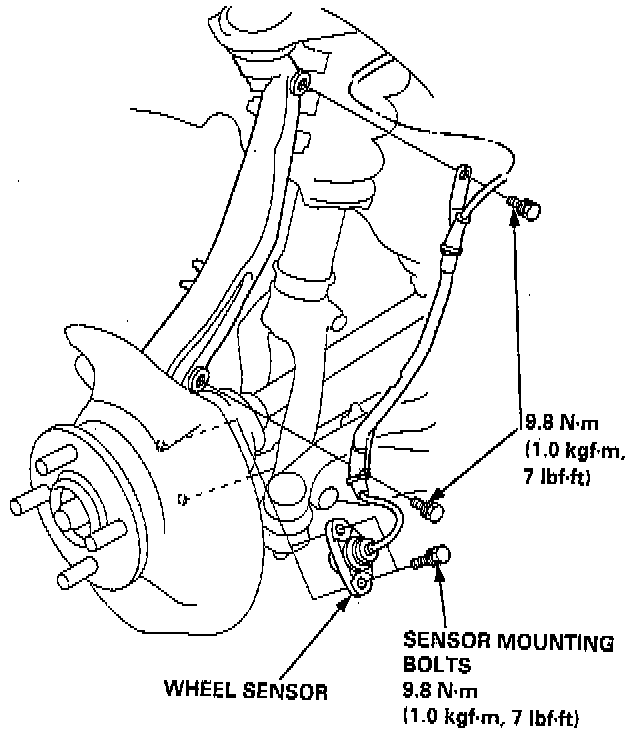
11. Remove the wheel sensor from the knuckle (for cars with ABS).
NOTE: Do not disconnect the wheel sensor connector. Use the special tool to separate the ball joints from the suspension or steering arm.
CAUTION: Be careful not to damage the ball joint boot.
12. Clean any dirt or grease off the ball joint.
13. Remove the cotter pin from the steering arm and remove the nut.

14. Apply grease to the special tool on the areas shown. This will ease installation of the tool and prevent damage to the pressure bolt threads.
15. Install a 10 mm hex nut on the ball joint. Be sure that the hex nut is flush with the ball joint pin end to prevent damage to the threaded end of the ball joint.

16. Install the special tool as shown. Insert the jaws carefully, making sure you do not damage the ball joint boot. Adjust the jaw spacing by turning the pressure bolt.
NOTE: If necessary, apply penetrating type lubricant to loosen the ball joint.

17. Once the special tool is in place, turn the adjusting bolt as necessary to make the jaws parallel. Then hand-tighten the pressure bolt, and recheck the jaws to make sure they are still Parallel.
NOTE: After making the adjustment to the adjusting bolt, be sure the head of the adjusting bolt is in this position to the allow the jaw to pivot.
18. With a wrench, tighten the pressure bolt until the ball joint shaft pops loose from the steering arm. Wear eye protection. The ball joint can break loose suddenly and scatter dirt or other debris in your eyes.
19. Remove the tool, then remove the nut from the end of the ball joint and pull the ball joint out of the steering/suspension arm. Inspect the ball joint boot and replace it if damaged.

20. Remove the cotter pin from the lower arm ball joint castle nut, and remove the nut.
21. Install a 12 mm hex nut on the ball joint. Be sure that the hex nut is flush with the ball joint pin end, or the threaded section of the ball joint pin might be damaged by the ball joint remover.
22. Use the special tool to separate the ball joint and lower arm.
NOTE: If necessary, apply penetrating type lubricant to loosen the ball joint.

23. Remove the cotter pin from the upper ball joint castle nut, and remove the nut.
24. Install the 12 mm hex nut on the ball joint. Be sure that the hex nut is flush with the ball joint pin end, or the threaded section of the ball joint pin might be damaged by the ball joint remover.
25. Use the special tool to separate the ball joint and knuckle.
NOTE: If necessary, apply penetrating type lubricant to loosen the ball joint.

26. Pull the knuckle outward and remove the driveshaft outboard joint from the knuckle by tapping the driveshaft end with a plastic hammer, then remove the knuckle.
NOTE: Replace the bearing with a new one after removal.
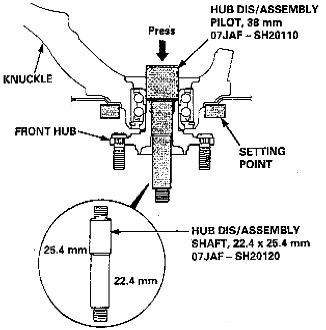
27. Separate the wheel hub from the knuckle using the special tools and a hydraulic press.
CAUTION:
- Take care not to distort the splash guard.
- Hold onto the wheel hub to keep it from falling when pressed clear.
- To prevent damage to the tool, make sure the threads are fully engaged before pressing.

28. Remove the circlip and the splash guard from the knuckle.

29. Press the wheel bearing out of the knuckle using the special tools and a press as shown.

30. Press the wheel bearing inner race from the wheel hub using the special tools, a bearing separator, and a press as shown.
NOTE: Wash the knuckle and wheel hub thoroughly in high flash point solvent before reassembly.

31. Press a new wheel bearing into the knuckle using the special tools and a press as shown.
NOTE: Place the wheel bearing on the knuckle with the pack seal (metal color) toward the inside. Be careful not to damage the sleeve of the pack seal.
32. Install the circlip securely in the knuckle groove.

33. Install the splash guard and tighten the screws.

34. Install the wheel hub on the knuckle using the special tools shown and a hydraulic press as shown.
CAUTION: Take care not to distort the splash guard.
35. Install the knuckle in the reverse order of removal, and pay particular attention to the following items:
a. Be careful not to damage the ball joint boots when installing the knuckle.
b. Torque all mounting hardware to the specified torque values.
c. Torque the castle nuts to the lower torque specifications, then tighten them only far enough to align the slot with the pin hole. Do not align the castle nut by loosening.
d. Install new cotter pins on the castle nuts after torquing.
e. Avoid twisting the sensor wires when installing the wheel sensor.
f. Before installing the brake disc, clean the mating surfaces of the front wheel hub and the inside of the brake disc.
g. Before installing the wheel, clean the mating surface of the brake disc and the inside of the wheel.
h. Check the front wheel alignment, and adjust it if necessary.