Assembly
IF THE CRANKSHAFT IS ALREADY INSTALLED.1. Set the crankshaft to BDC for each cylinder.
2. Remove the connecting rod caps, then install the ring compressor, and check that the bearing is securely in place.

3. Position the arrow (A) and the mark (B) facing the timing belt side of the engine.

4. Position the piston in the cylinder, and tap it in using the wooden handle of a hammer (A). Maintain downward force on the ring compressor (B) to prevent the rings from expanding before entering the cylinder bore.
5. Stop after the ring compressor pops free, and check the connecting rod-to-crank journal alignment before pushing the piston into place.
6. Check the connecting rod bearing clearance with plastigage.
7. Apply engine oil to the bolt threads, then install the rod caps with bearings. Torque the bolts to 20 Nm (2.0 kgf.m, 14 ft. lbs.).

8. Mark the connecting rod (A) and bolt head (B) as shown.
9. Tighten the bolt until the mark on the bolt head lines up with the mark on the connecting rod (turn the bolt 90°).
IF THE CRANKSHAFT IS NOT INSTALLED.
1. Remove the connecting rod caps, then install the ring compressor, and check that the bearing is securely in place.

2. Position the arrow (A) and the mark (B) facing the timing belt side of the engine.
3. Position the piston in the cylinder, and tap it in using the wooden handle of a hammer (A). Maintain downward force on the ring compressor (B) to prevent the rings from expanding before entering the cylinder bore.
4. Position all pistons at top dead center.
CRANKSHAFT AND BALANCER SHAFT INSTALLATION
Special Tools Required
- Driver 07749-0010000
- Driver Attachment 07948-SB00101
1. Apply a coat of engine oil to the main bearings and rod bearings.
2. Install the bearing halves in the cylinder block and connecting rods.
3. Hold the crankshaft so rod journal No. 2 and rod journal No. 3 are straight up.

4. Install the thrust washers (A) in the No. 4 journal of the cylinder block.
5. Lower the crankshaft into the block, seating the rod journals into connecting rod No.1 (B) and connecting rod No. 4 (C). Install the connecting rod caps and bolts finger tight.
6. Rotate the crankshaft clockwise, seat the journals into connecting rod No. 2 (D) and connecting rod No. 3 (E). Install the connecting rod caps and bolts finger tight. Install caps so the bearing recess is on the same side as the recess in the rod.
7. Check the connecting rod bearing clearance with plastigage.
8. Apply engine oil to the bolt threads, then install the rod caps with bearings, and torque the bolts to 20 Nm (2.0 kgf.m, 14 ft. lbs.).
9. Mark the connecting rod (A) and bolt head (B) as shown.
10. Tighten the bolt until the mark on the bolt head lines up with the mark on the connecting rod (turn the bolt 90°).
11. Check main bearing clearance with plastigage.
12. Install the main bearing caps and bearing cap bridge. Coat the bolt threads with engine oil.

13. Check clearances with plastigage, then tighten the 11 mm bolts in two steps. In the first step, tighten all bolts in sequence to about 29 Nm (3.0 kgf.m, 22 ft. lbs.). in the final step, tighten in the same sequence to 78 Nm (8.0 kgf.m, 58 ft. lbs.).

14. Tighten the 6 mm bolts in sequence to 12 Nm (1.2 kgf.m, 8.7 ft. lbs.).
NOTE: Whenever any crankshaft or connecting rod bearing is replaced, it is necessary after reassembly to run the engine at idling speed until it reaches normal operating temperature, then continue to run it for approximately 15 minutes.

15. Drive the crankshaft oil seal squarely into the right side cover.

16. Confirm that the clearance is equal all the way around with a feeler gauge.
Clearance: 0.5 - 0.8 mm (0.02 - 0.03 inch)
17. Clean and dry the right side cover mating surfaces. Apply a light coat of oil to the crankshaft and to the lip of the seal.

18. Apply liquid gasket, part No. 08718-0001 or 08718-0003, evenly to the block mating surface of the right side cover and to the inner threads of the bolt holes. Install the dowel pins (A) and the right side cover (B) on the cylinder block.
NOTE: Do not install the parts if five minutes or more have elapsed since applying the liquid gasket. Instead, reapply liquid gasket after removing the old residue.
19. After assembly, wait at least 30 minutes before filling the engine with oil.
Rear Shaft Retainer Torque:
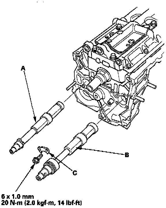
20. Install the rear balancer shaft (A) and the front balancer shaft (B) into the block, then install the retainer (C).
21. Clean and dry the oil pump mating surfaces.

22. Install the oil pump (A).
-1 Install a new crankshaft oil seal in the oil pump.
-2 Apply liquid gasket part, No. 08718-0001 or 08718-0003, evenly to the block mating surface of the oil pump and to the inner threads of the bolt holes.
-3 Grease the lips of the oil seals and apply oil to the new O-ring (B).
-4 Install the dowel pins (C), then align the inner rotor with the crankshaft and install the oil pump.
-5 Clean the excess grease off the crankshaft and balancer shaft and check the seals for distortion.
23. Install the baffle plate (D), then install the oil screen (E).
Front Shaft Gear:

24. Hold the front balancer shaft with a screwdriver (A), then install the timing balancer belt driven pulley (B).

25. Before installing the balancer driven gear (A) and the balancer gear case (B) apply molybdenum disulfide (C) to the thrust surfaces of the balancer gears as shown.
Rear Shaft Driven Gear:

26. Install the balancer driven gear.
-1 Remove the bolt (A) and washer (B) from the maintenance hole (C).
-2 Scribe a line on a 6 x 100 mm bolt, 74 mm from the end.
-3 Insert the bolt in the maintenance hole and into the hole in the rear balancer shaft (D) up to the line you scribed.
-4 Install the balancer driven gear (E).
Rear Shaft Gear Balancer Gear Case:

27. Install the balancer gear case (A).
-1 Apply clean engine oil to the new O-ring (B).
-2 Hold the rear balancer shaft with the 6 x 100 mm bolt.
-3 Align the notch (C) on the pulley edge with the pointer (D) on the gear case.
-4 Install the near case (A).

28. After installation, make sure the pulley pointer (A) aligns with the oil pump pointer (B).
29. Clean and dry the cylinder block mating surfaces.

30. Apply liquid gasket part No. 08718-0009 evenly to the cylinder block mating surface of the oil pan and to the inner threads of the bolt holes. Install the oil pan.
NOTE:
- Apply liquid gasket in a 4 mm wide bead.
- Apply a second bead where the two ends of the first bead meet.

31. Tighten the bolts/nuts in two or three steps. In the final step, tighten all bolts/nuts, in sequence, to 12 Nm (1.2 kgf.m, 8.7 ft. lbs.).
PULLEY END CRANKSHAFT SEAL INSTALLATION - IN-CAR
Special Tools Required
- Seal Driver 07LAD-PT3010A
1. Dry the crankshaft oil seal housing.
2. Apply a light coat of grease to the crankshaft and to the lip of the seal.

3. Using the seal driver, drive in the crankshaft oil seal until the driver bottoms against the oil pump. When the seal is in place, clean any excess grease off the crankshaft and check that the oil seal lip is not distorted.
BALANCER SHAFT SEALS INSTALLATION -IN-CAR
Special Tools Required
- Hub Assembly Guide Attachment 07GAF-SE00200
- Attachment, 30 mm I.D. 07746-0030300
1. Dry the crankshaft oil seal housing.
2. Apply a light coat of grease to the balancer shaft and to the lip of the seal.

3. Using the special tools, drive in the front balancer shaft oil seal until the driver bottoms against the oil pump. When the seal is in place, clean any excess grease off the balancer shaft, and check that the oil seal lip is not distorted.
TRANSMISSION END CRANKSHAFT SEAL INSTALLATION - IN-CAR
Special Tools Required
- Driver 07749-0010000
- Driver Attachment 07948-SB00101
1. Dry the crankshaft oil seal housing.
2. Apply a light coat of grease to the crankshaft and to the lip of the seal.

3. Using the special tools, drive the crankshaft oil seal into the right side cover to the point where the clearance between the bottom of the crankshaft oil seal and right side cover is 0.5 - 0.8 mm (0.02 - 0.03 inch). Align the hole in the driver attachment with the pin on the crankshaft.
4. Clean any excess grease off the crankshaft, and check that the oil seal lip is not distorted.