Shift Lock System Circuit Troubleshooting
Troubleshooting1. Press the brake pedal.
Are the brake lights ON?
YES - Go to step 2.
NO - Repair faulty brake light circuit.
2. Turn the ignition switch ON (II), and shift to P position.
3. Press the brake pedal, and release the accelerator pedal.
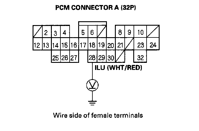
4. Measure the voltage between the A28 terminal and body ground.
Is there battery voltage?
YES - Go to step 5.
NO - Go to step 8.
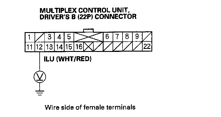
5. Measure the voltage between the B12 terminal of the multiplex control unit, driver's B (22P) connector and body ground with the throttle released and the brake pedal pressed.
Is there battery voltage?
YES - Go to step 6.
NO - Repair open in the wire between the A28 terminal of the PCM and B12 terminal of the driver's multiplex control unites
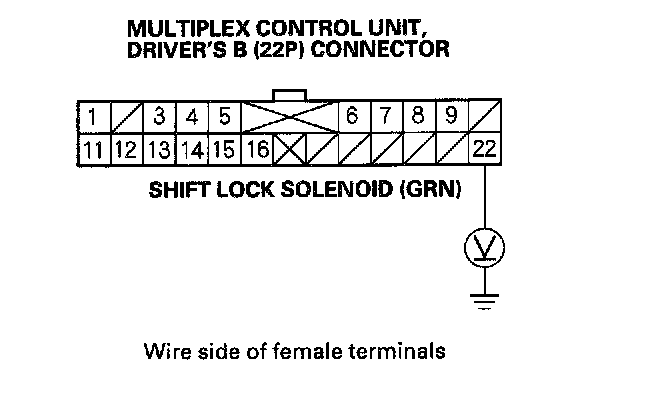
6. Measure the voltage between the B22 terminal of the multiplex control unit, driver's B (22P) connector and body ground.
Is there battery voltage?
YES - Go to step 7.
NO - Repair open in the wire between the B22 terminal of the driver's multiplex control unit and the driver's under-dash fuse No. 9 (via the shift lock solenoid).
7. Turn the ignition switch ON (II), and move the shift lever to P position.
Dose the P indicator in the gauge assembly illuminate?
YES - Check for loose terminal fit to the driver's multiplex control unit B12 and B22 terminal wires. If necessary, substitute a known-good driver's multiplex control unit.
NO - Repair open in the P position switch circuit from the driver's under-dash fuse/relay box K10 (BLK/BLU) wire to ground (G101).
8. Turn the ignition switch OFF.
9. Disconnect PCM connectors A (32P) and B (25P).
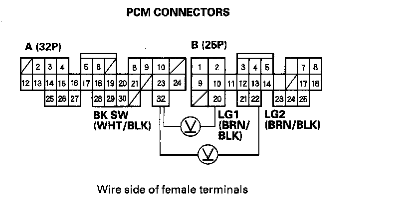
10. Measure the voltage between the A32 and B20 or B22 terminals while pressing the brake pedal.
Is there battery voltage?
YES - Go to step 11.
NO - Repair open in the wire between the A32 terminal and the brake pedal position switch.
11. Reconnect PCM connectors A (32P) and B (25P).
12. Turn the ignition switch ON (II).
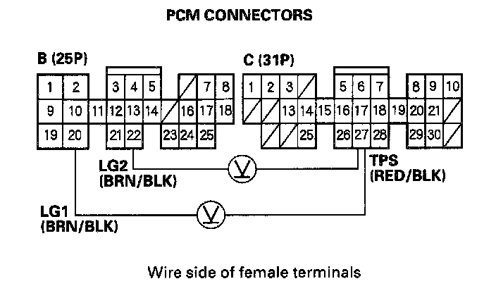
13. Measure the voltage between the C27 and B20 or B22 terminals.
Is there about 0.5 V (throttle fully closed)?
YES - Check for loose terminal fit in the PCM connectors. If necessary, substitute a known-good PCM and recheck.
NO - Go to step 14.
14. Turn the ignition switch OFF.
15. Disconnect the throttle position sensor connector.
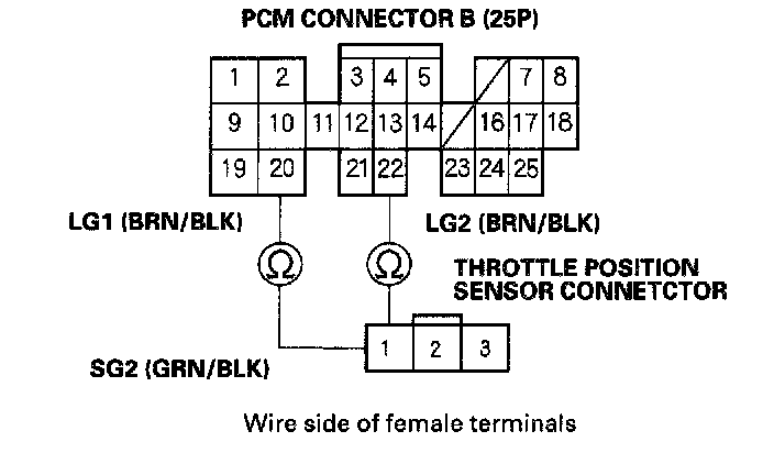
16. Check for continuity between the No. 1 terminal of the throttle position sensor and the B20 or B22 terminal of the PCM.
Is there continuity?
YES - Repair throttle position sensor installation.
NO - Go to step 17.
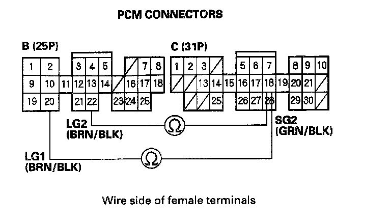
17. Check for continuity between the C18 and B20 or B22 terminals.
Is there continuity?
YES - Repair open in the wire between the C18 terminal and the throttle position sensor.
NO - Check for loose terminal fit in the PCM connectors. If necessary, substitute a known-good PCM and rechecked