[D4] Indicator Circuit Troubleshooting
Troubleshooting1. Turn the ignition switch ON (II), and watch the D4 indicator.
Does the D4 indicator come on and stay on?
YES - Go to step 2.
NO - If the light comes on for about 2 seconds and then goes off, it's OK. If it doesn't come on at all, go to step 16.
2. Make sure the Honda PGM Tester is not connected to the Data Link Connector (DLC).
3. Turn the ignition switch OFF.
4. Disconnect the battery negative terminal.
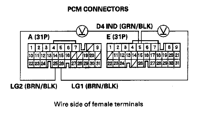
5. Disconnect PCM connector C (22P) and E (31P).
6. Reconnect the battery negative terminal.
7. Turn the ignition switch ON (II).
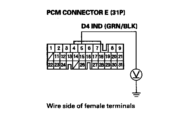
8. Measure the voltage between PCM connector E5 terminal and body ground.
Is there voltage?
YES - Repair short to power in the wire between PCM connector terminal E5 and the gauge assembly.
NO - Go to step 9.
9. Turn the ignition switch OFF.
10. Disconnect the battery negative terminal.
11. Reconnect PCM connector C (22P) and E (31P).
12. Reconnect the battery negative terminal.
13. Turn the ignition switch ON (II).
14. Shift to any position other than D4.
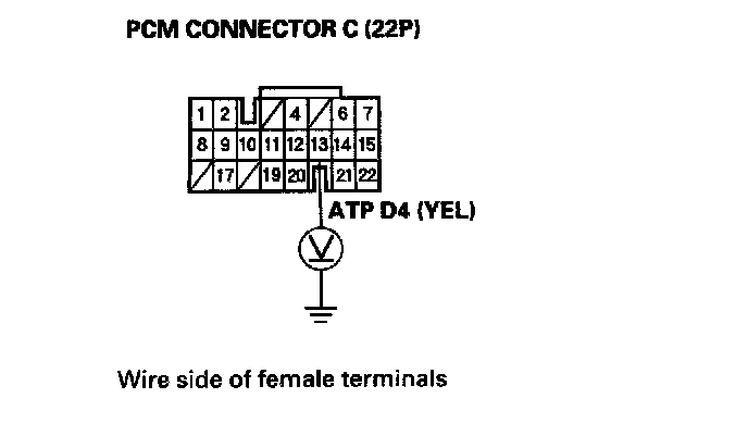
15. Measure the voltage between PCM connector terminal C13 and body ground.
Is there voltage?
YES - Faulty PCM or gauge assembly.
NO - Check for a short to ground in the wire between PCM connector terminal C13 and the transmission range switch. If the wire is OK, check the transmission range switch.
16. Make sure the Honda PGM Tester is not connected to the DLC.
17. Shift to D4 position.
Does the D4 indicator come on?
YES - Check for loose terminal fit in the PCM connectors and recheck the D4 indicator several times. If the problem is intermittent, substitute a known-good PCM and recheck. If the light then works OK every time, replace the original PCM.
NO - Go to step 18.
18. Turn the ignition switch OFF.
19. Disconnect the battery negative terminal.
20. Disconnect PCM connector A (31P).
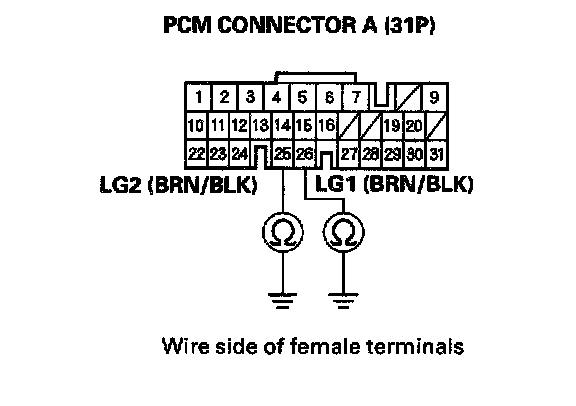
21. Check for continuity between PCM connector terminal A25 and body ground, and between terminal A26 and body ground.
Is there continuity?
YES - Go to step 22.
NO - Repair open in the wire(s) between PCM connector terminals A25 or A26, and ground (G101), or repair poor ground (G101).
22. Reconnect the battery negative terminal.
23. Turn the ignition switch ON (II).
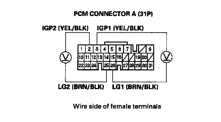
24. Measure the voltage between PCM connector terminals A2 and A25, and between terminals As and A26.
Is there battery voltage?
YES - Go to step 25.
NO - Repair open or short in the wire between PCM connector terminals A2 or A3 and the PGM-FI main relay.
25. Turn the ignition switch OFF.
26. Disconnect the battery negative terminal.
27. Reconnect PCM connector A (31P).
28. Connect the digital multimeter between PCM connector terminals E5 and A25 or A26.
29. Reconnect the battery negative terminal.
30. Turn the ignition switch ON (II).
Is there voltage for at least 2 seconds?
YES - Check for an open in the wire between PCM connector terminal E5 and the gauge assembly. If the wire is OK, check for a faulty D4 indicator bulb or a faulty printed circuit board in the gauge assembly.
NO - Go to step 31.
31. Turn the ignition switch OFF.
32. Disconnect the battery negative terminal.
33. Disconnect PCM connector E (31P).
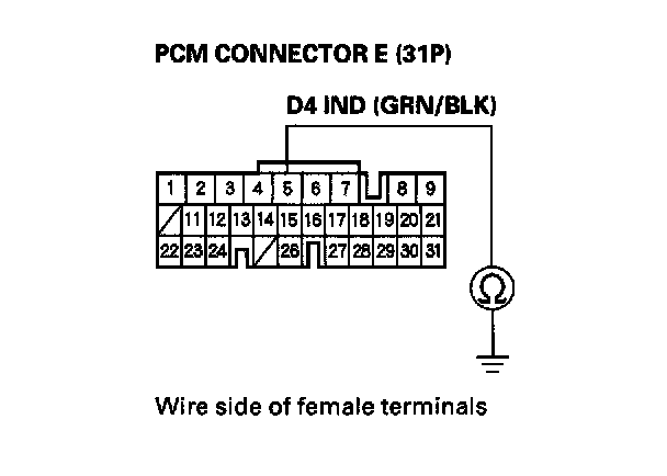
34. Check for continuity between PCM connector terminal E5 and body ground.
Is there continuity?
YES - Repair short to ground in the wire between PCM connector terminal E5 and the gauge assembly.
NO - Check for loose terminal fit in the PCM connectors. Check the transmission range switch. If necessary, substitute a known-good PCM and recheck.