Part 1
System DescriptionGeneral Operation
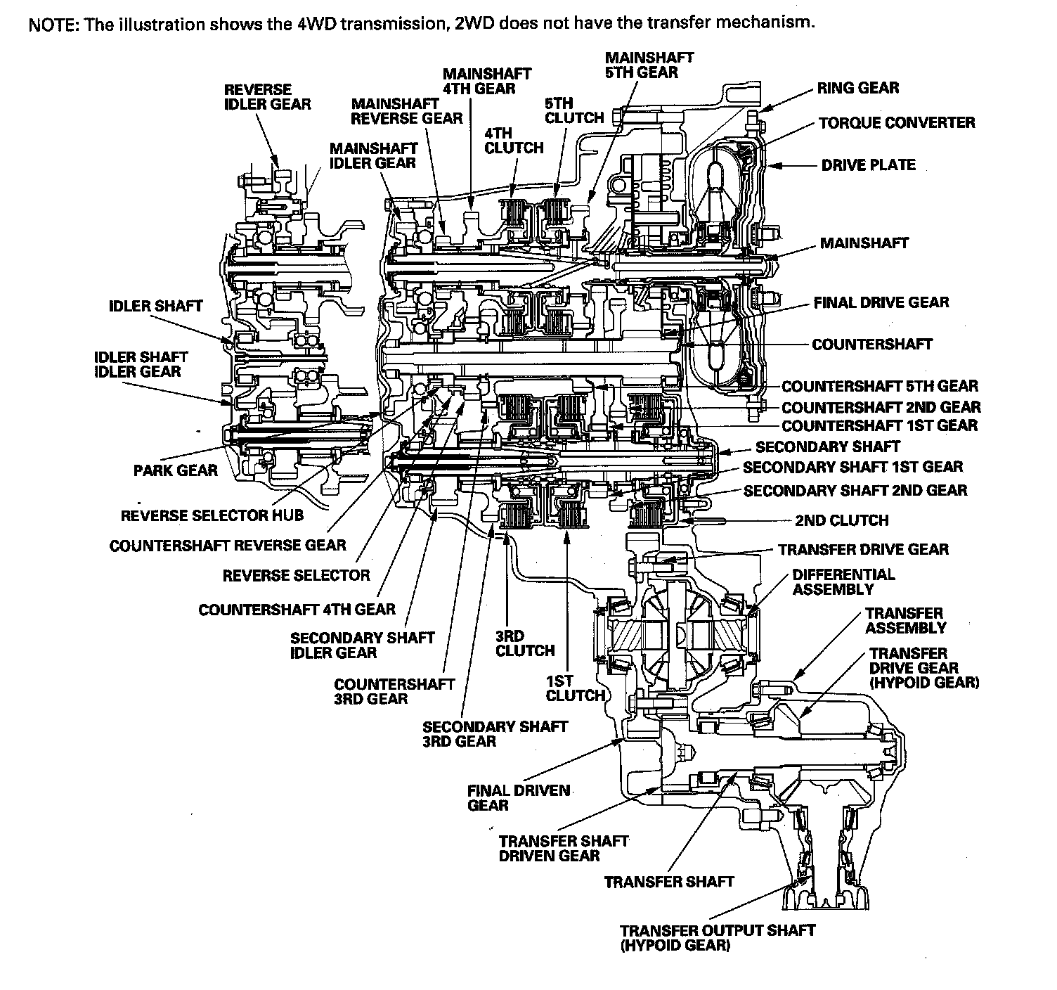
The automatic transmission is a combination of a 3-element torque converter and triple-shaft electronically controlled unit which provides 5 speeds forward and 1 reverse. The entire unit is positioned in line with the engine.
Torque Converter, Gears, and Clutches
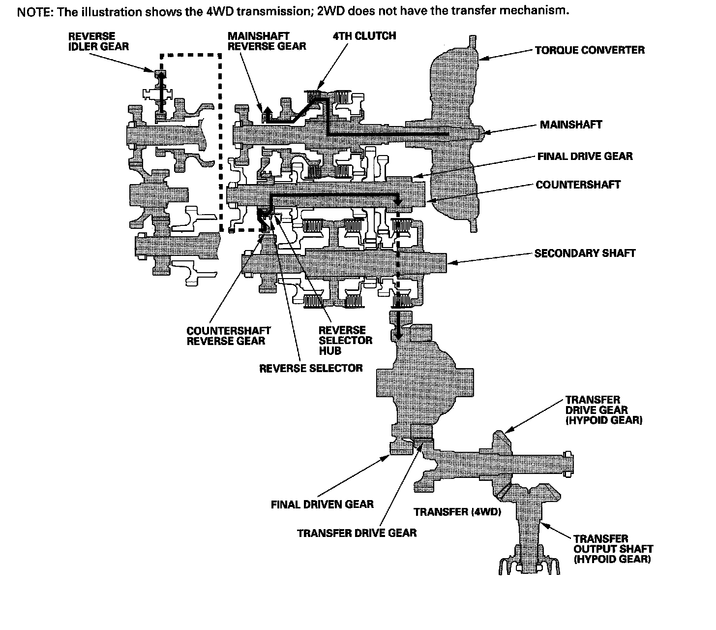
The torque converter consists of a pump, turbine, and stator assembly in a single unit. The converter housing (pump) is connected to the engine crankshaft and turns as the engine turns. Around the outside of the torque converter is a ring gear which meshes with the starter pinion when the engine is being started. The entire torque converter assembly serves as a flywheel while transmitting power to the transmission mainshaft, the transmission has three parallel shafts; the mainshaft, the countershaft, and the secondary shaft. The mainshaft is in line with the engine crankshaft, and includes the 4th and 5th clutches, and gears for 5th, 4th, reverse, and idler. The mainshaft reverse gear is integral with the mainshaft 4th gear. The countershaft includes the gears for 1st, 2nd, 3rd, 4th, 5th, reverse, park, and the final drive. The final drive gear is integral with the countershaft. The countershaft 4th gear and the countershaft reverse gear can be locked to the countershaft providing 4th or reverse gear, depending on which way the selector is moved. The secondary shaft includes the 1st, 2nd, and 3rd clutches, and gears for 1st, 2nd, 3rd, and idler. The idler shaft is located between the mainshaft and secondary shaft, and the idler gear transmits power between the mainshaft and the secondary shaft. The gears on the mainshaft and the secondary shaft are in constant mesh with those on the countershaft. When certain combinations of gears in the transmission are engaged by the clutches, power is transmitted through the mainshaft, then to the secondary shaft to the countershaft or through the mainshaft to the countershaft to provide drive.
Electronic Control
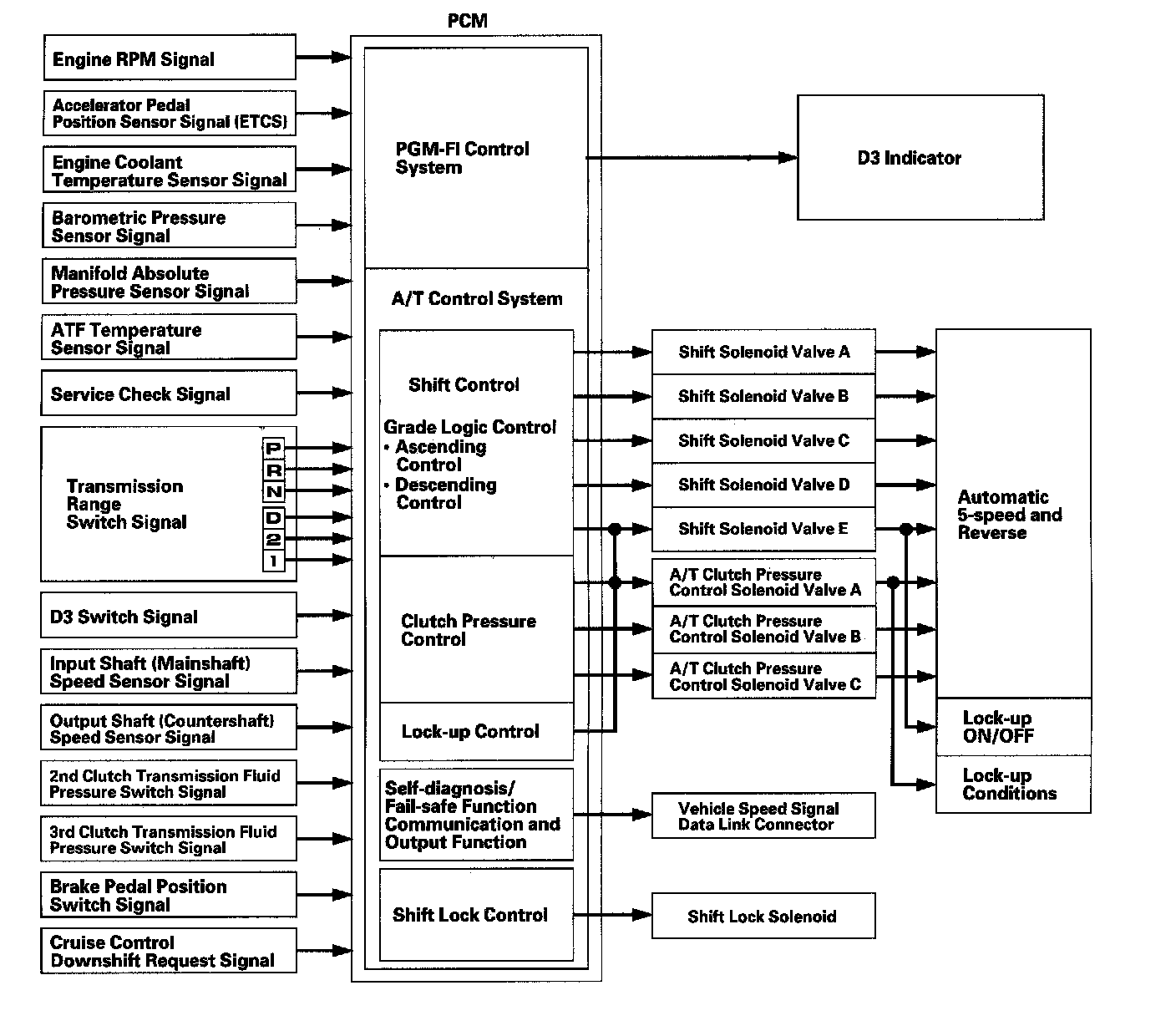
The electronic control system consists of the powertrain control module (PCM), sensors, and solenoid valves. Shifting and lock-up are electronically controlled for comfortable driving under all conditions. The PCM is located under the hood next to the battery.
Hydraulic Control
The valve bodies include the main valve body, the regulator valve body, and the servo body. They are bolted to the torque converter housing. The main valve body contains the manual valve, the shift valves A, B, C, and E, the relief valve, the lock-up control valve, the cooler check valve, the servo control valve, and the ATF pump gears. The regulator valve body contains the regulator valve, the torque converter check valve, lock-up shift valve, and the 1st and 3rd accumulators. The servo body contains the servo valve, the shift valve D, accumulators for 2nd, 4th, and 5th, and shift solenoid valves for A, B, C, D, and E. Fluid from the regulator passes through the manual valve to the various control valves. The 1st, 3rd, 5th clutches receive fluid from their respective feed pipes, and the 2nd and the 4th clutches receive fluid from the internal hydraulic circuit.
Shift Control Mechanism
The PCM controls shift solenoid valves A, B, C, D, and E, and the A/T clutch pressure control solenoid valves A, B, and C, while receiving input signals from various sensors and switches located throughout the engine and transmission. The shift solenoid valves shift the positions of the shift valves to switch the port leading hydraulic pressure to the clutch. The A/T clutch pressure control solenoid valves A, B, and C regulate their respective pressure, and pressurize to the clutches to engage it and its corresponding gear. The pressures of the A/T clutch pressure control solenoid valves also apply to the shift valves to switch the port.
Lock-up Mechanism
The lock-up mechanism operates in the D position (2nd, 3rd, 4th, and 5th), and in D position D3 driving mode (2nd and 3rd). The pressurized fluid is drained from the back of the torque converter through a fluid passage, causing the torque converter clutch piston to be held against the torque converter cover. As this takes place, the mainshaft rotates at the same speed as the engine crankshaft. Together with the hydraulic control, the PCM optimizes the timing and volume of the lock-up mechanism. When the shift solenoid valve E is turned on by the PCM, shift solenoid valve E pressure switches the lock-up shift valve on and off. The A/T clutch pressure control solenoid valve A and the lock-up control valve control the volume of the lock-up conditions.
Gear Selection
The shift lever has six positions; P: PARK, R: REVERSE, N: NEUTRAL, D: DRIVE 1st through 5th gear range, and 1st through 3rd gear range with D3 driving mode, 2: 2nd gear, and 1: 1st gear.
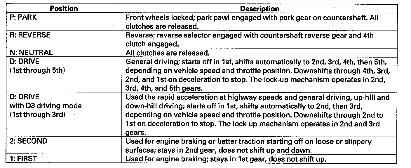
Starting is possible only in the P and N positions because of a slide-type neutral-safety switch.
Automatic Transmission (A/T) Gear Position Indicator
The A/T Gear Position indicator in the instrument panel shows which shift lever position has been selected without having to look down at the shift lever.
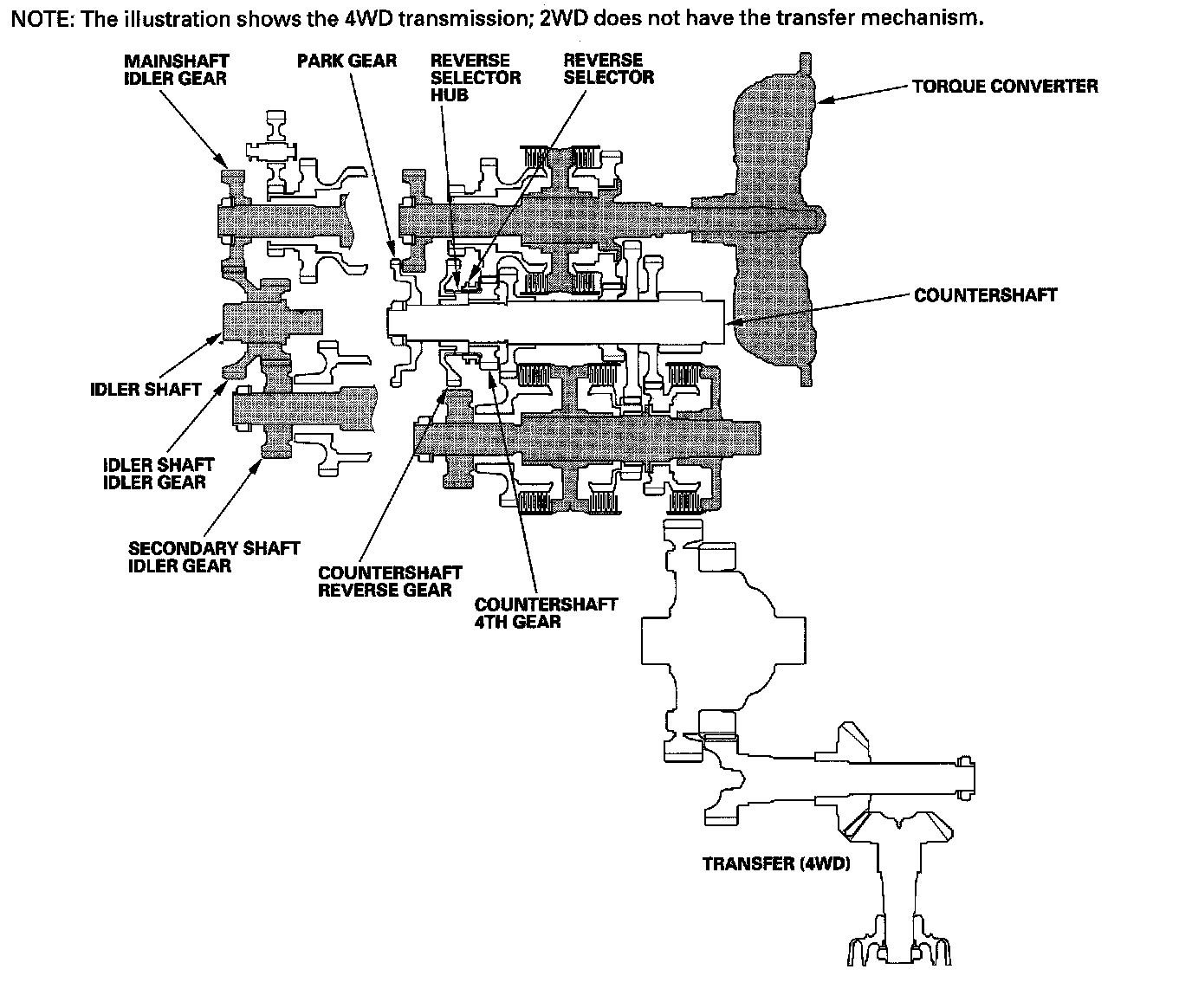
Transfer Mechanism (4WD)
The transfer mechanism consists of the transfer drive gear on the differential, the transfer shaft, the transfer drive gear (hypoid gear), the transfer output shaft (hypoid gear), and the companion flange. The transfer mechanism assembly is on the rear of the transmission, beside the differential. The transfer drive gear on the differential drives the transfer shaft and transfer drive gear (hypoid gear), and the transfer drive gear (hypoid gear) drives the transfer output shaft (hypoid gear). Power is transmitted from the transfer drive gear on the differential to the rear differential via the transfer shaft and the propeller shaft.
Clutches and Gears
The 5-speed automatic transmission uses hydraulically-actuated clutches to engage or disengage the transmission gears. When hydraulic pressure is introduced into the clutch drum, the clutch piston moves. This presses the friction discs and steel plates together, locking them so they don't slip. Power is then transmitted through the engaged clutch pack to its hub-mounted gear. Likewise, when the hydraulic pressure is bled from the clutch pack, the piston releases the friction discs and the steel plates, and they are free to slide past each other. This allows the gear to spin independently on its shaft, transmitting no power.
1st Clutch
The 1st clutch engages/disengages 1st gear, and is located at the middle of the secondary shaft. The 1st clutch is joined back-to-back to the 3rd clutch. The 1st clutch is supplied hydraulic pressure by its ATF feed pipe within the secondary shaft.
2nd Clutch
The 2nd clutch engages/disengages 2nd gear, and is located at the end of the secondary shaft, opposite the end cover. The 2nd clutch is supplied hydraulic pressure by a circuit connected to the internal hydraulic circuit.
3rd Clutch
The 3rd clutch engages/disengages 3rd gear, and is located at the middle of the secondary shaft. The 3rd clutch is joined back-to-back to the 1st clutch. The 3rd clutch is supplied hydraulic pressure by its ATF feed pipe within the secondary shaft.
4th Clutch
The 4th clutch engages/disengages 4th gear, as well as reverse gear, and is located at the middle of the mainshaft. The 4th clutch is joined back-to-back to the 5th clutch. The 4th clutch is supplied hydraulic pressure by its ATF feed pipe within the mainshaft.
5th Clutch
The 5th clutch engages/disengages 5th gear, and is located at the middle of the mainshaft. The 5th clutch is joined back-to-back to the 4th clutch. The 5th clutch is supplied hydraulic pressure by its ATF feed pipe within the mainshaft.
Gear operation
Gears on the mainshaft:
^ 4th gear engages/disengages with the mainshaft by the 4th clutch.
^ 5th gear engages/disengages with the mainshaft by the 5th clutch.
^ Reverse gear engages/disengages with the mainshaft by the 4th clutch.
^ Idler gear is splined with the mainshaft, and rotates with the mainshaft.
Gears on the countershaft:
^ Final drive gear is integral with the countershaft.
^ 1st, 2nd, 3rd, 5th, and park gears are splined with the countershaft, and rotate with the countershaft.
^ 4th gear and reverse gear rotate freely from the countershaft. The reverse selector engages 4th gear and reverse gear with the reverse selector hub. The reverse selector hub is splined to the countershaft so that the 4th gear and reverse gear engage with the countershaft.
Gears on the secondary shaft:
^ 1st gear engages/disengages with the secondary shaft by the 1st clutch.
^ 2nd gear engages/disengages with the secondary shaft by the 2nd clutch.
^ 3rd gear engages/disengages with the secondary shaft by the 3rd clutch.
^ Idler gear is splined with the secondary shaft, and rotates with the secondary shaft.
The idler gear on the idler shaft transmits power between the mainshaft and the secondary shaft.
The reverse idler gear transmits power from the mainshaft reverse gear to the countershaft reverse gear, and changes rotational direction of the countershaft to reverse.
Power Flow
P Position
Hydraulic pressure is not applied to the clutch. Power is not transmitted to the countershaft. The countershaft is locked by the park pawl, interlocking the park gear.
N Position
Engine power transmitted from the torque converter drives the mainshaft idler gear, the idler shaft idler gear, and the secondary shaft idler gear, but hydraulic pressure is not applied to the clutches. Power is not transmitted to the countershaft. In this position, the position of the reverse selector differs according to whether the shift lever shifted from the D or R position:
^ When shifted from the D position, the reverse selector engages with the countershaft 4th gear and the reverse selector hub, and the 4th gear engages with the countershaft.
^ When shifted from the R position, the reverse selector engages with the countershaft reverse gear and the reverse selector hub, and the reverse gear engages with the countershaft.
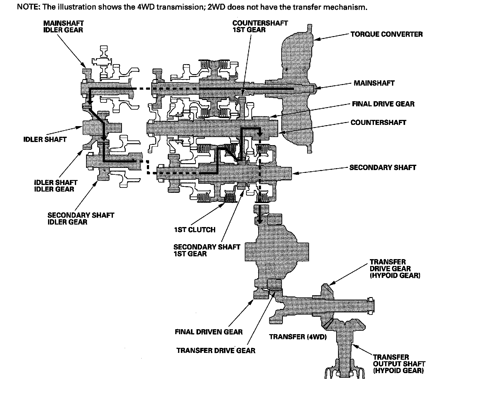
1st Gear
^ Hydraulic pressure is applied to the 1st clutch, then the 1st clutch engages the secondary shaft 1st gear with the secondary shaft.
^ The mainshaft idler gear drives the secondary shaft via the idler shaft idler gear and the secondary shaft idler gear.
^ The secondary shaft 1st gear drives the countershaft 1st gear and the countershaft.
^ Power is transmitted to the final drive gear, which in turn drives the final driven gear, and the transfer drive gear (4WD).
^ 4WD: The transfer drive gear drives the transfer drive gear (hypoid gear) and the transfer output shaft (hypoid gear).
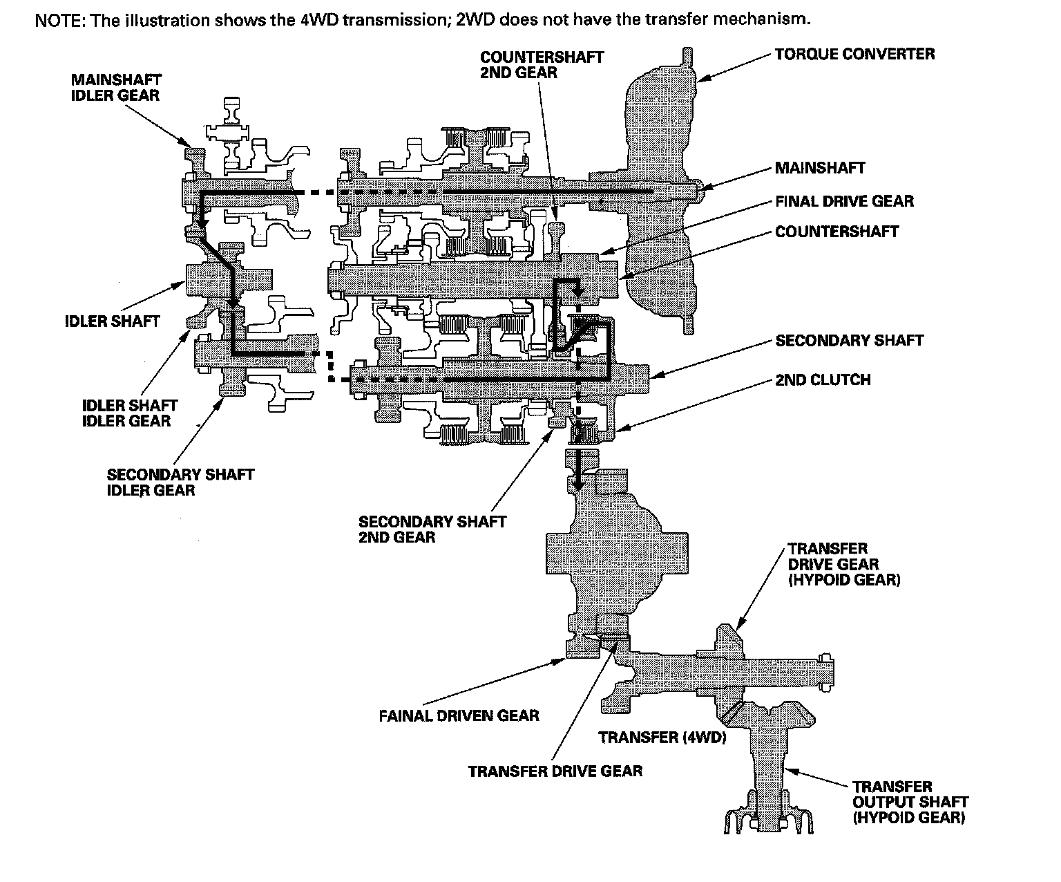
2nd Gear
^ Hydraulic pressure is applied to the 2nd clutch, then the 2nd clutch engages the secondary shaft 2nd gear with the secondary shaft.
^ The mainshaft idler gear drives the secondary shaft via the idler shaft idler gear and the secondary shaft idler gear.
^ The secondary shaft 2nd gear drives the countershaft 2nd gear and the countershaft.
^ Power is transmitted to the final drive gear, which in turn drives the final driven gear, and the transfer drive gear (4WD).
^ 4WD: The transfer drive gear drives the transfer drive gear (hypoid gear) and the transfer output shaft (hypoid gear).
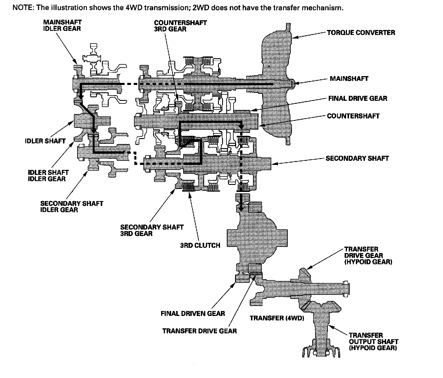
3rd Gear
^ Hydraulic pressure is applied to the 3rd clutch, then the 3rd clutch engages the secondary shaft 3rd gear with the secondary shaft.
^ The mainshaft idler gear drives the secondary shaft via the idler shaft idler gear and secondary shaft idler gear.
^ The secondary shaft 3rd gear drives the countershaft 3rd gear and the countershaft.
^ Power is transmitted to the final drive gear, which in turn drives the final driven gear, and the transfer drive gear (4WD).
^ 4WD: The transfer drive gear drives the transfer drive gear (hypoid gear) and the transfer output shaft (hypoid gear).
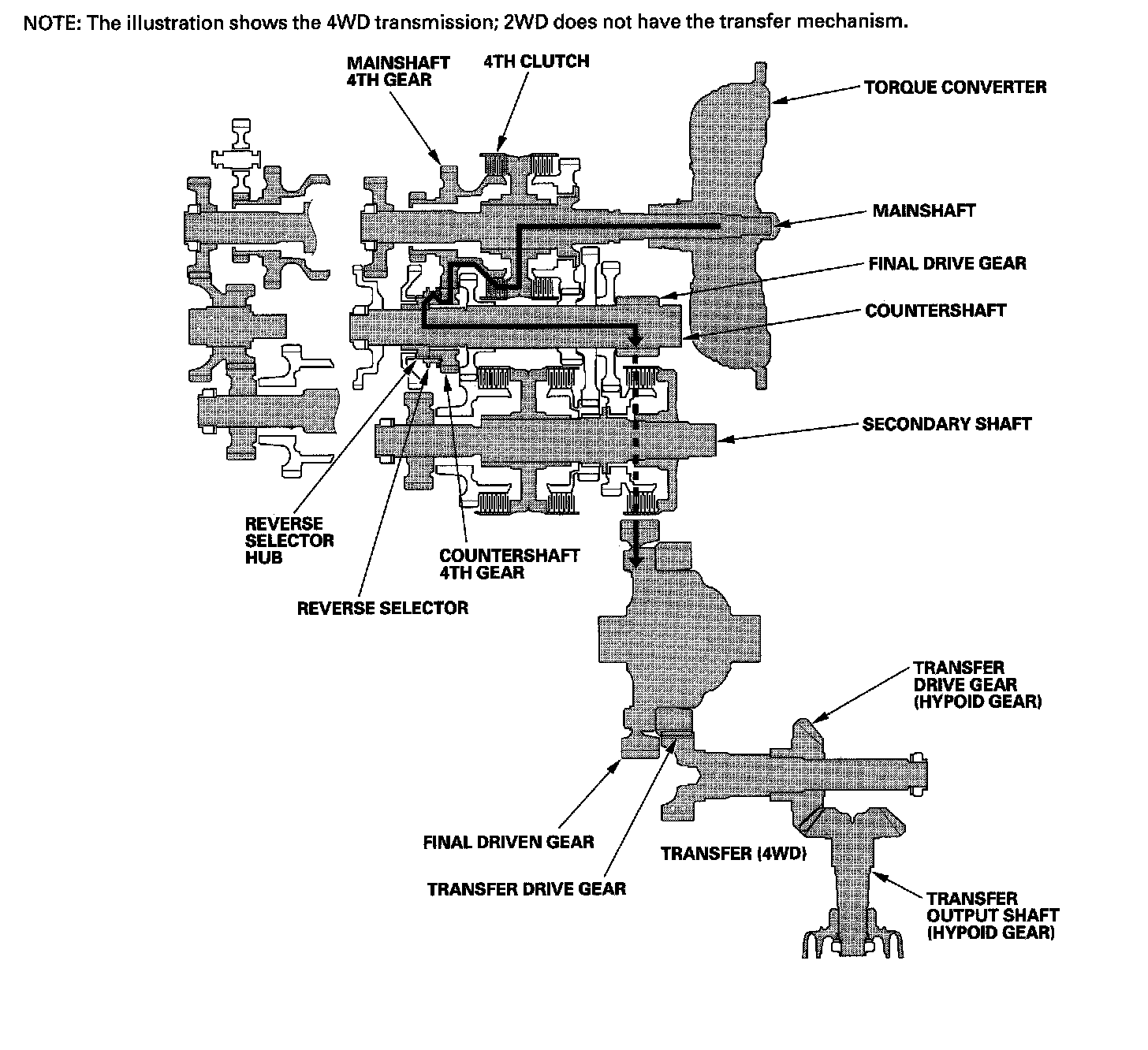
4th Gear
^ Hydraulic pressure is applied to the servo valve to engage the reverse selector with the countershaft 4th gear and reverse selector hub while the shift lever is in forward range (D, 2, and 1 positions).
^ Hydraulic pressure is also applied to the 4th clutch, then the 4th clutch engages the mainshaft 4th gear with the mainshaft.
^ The mainshaft 4th gear drives the countershaft 4th gear and the countershaft.
^ Power is transmitted to the final drive gear, which in turn drives the final driven gear, and the transfer drive gear (4WD).
^ 4WD: The transfer drive gear drives the transfer drive gear (hypoid gear) and the transfer output shaft (hypoid gear).
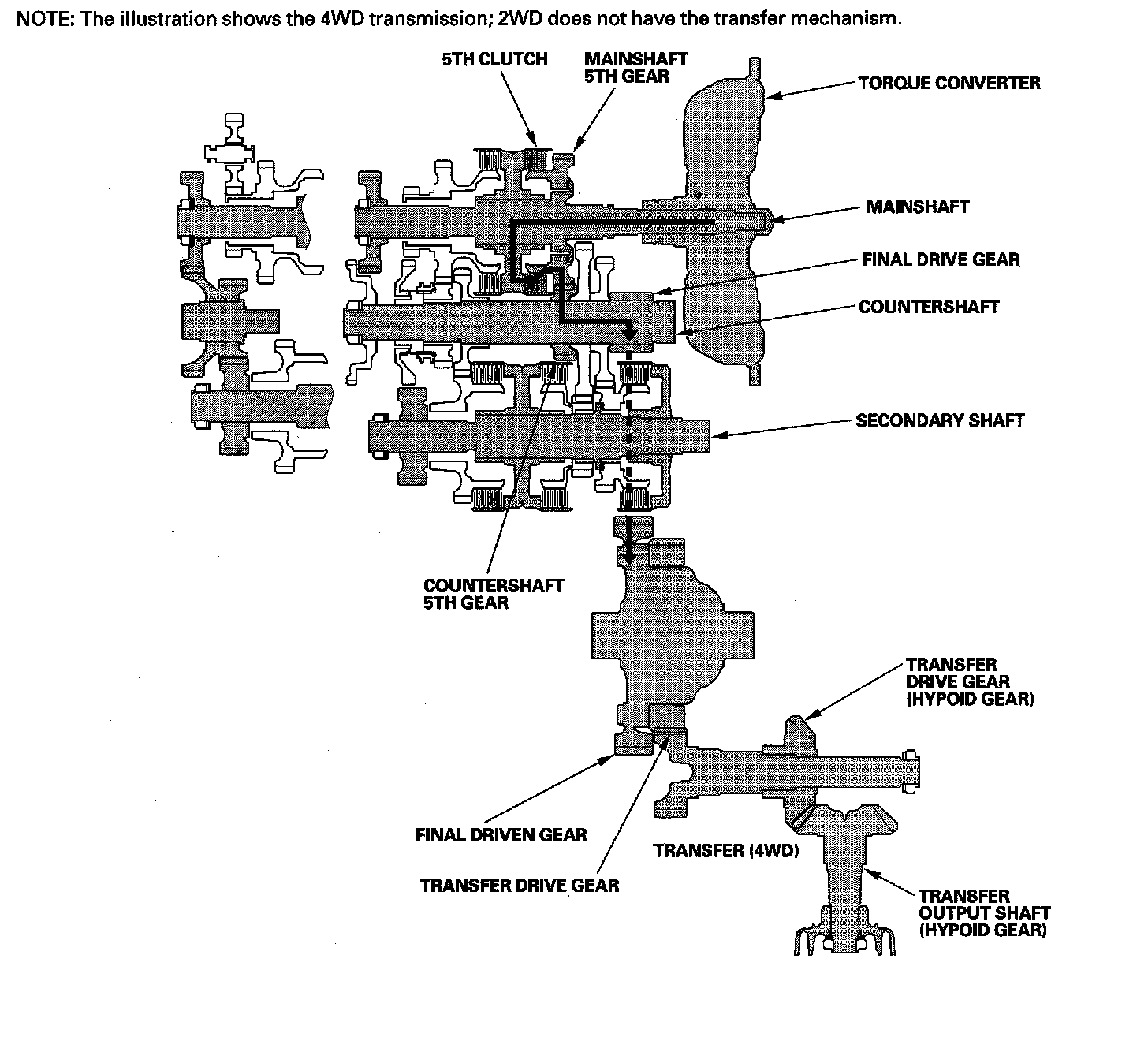
5th Gear
^ Hydraulic pressure is applied to the 5th clutch, then the 5th clutch engages the mainshaft 5th gear with the mainshaft.
^ The mainshaft 5th gear drives the countershaft 5th gear and the countershaft.
^ Power is transmitted to the final drive gear, which in turn drives the final driven gear, and the transfer drive gear (4WD).
^ 4WD: The transfer drive gear drives the transfer drive gear (hypoid gear) and the transfer output shaft (hypoid gear).
R Position
^ Hydraulic pressure is applied to the servo valve to engage the reverse selector with the countershaft reverse gear and reverse selector hub while the shift lever is in the R position.
^ Hydraulic pressure is also applied to the 4th clutch, then the 4th clutch engages the mainshaft reverse gear with the mainshaft.
^ The mainshaft reverse gear drives the countershaft reverse gear via the reverse idler gear.
^ The rotation direction of the countershaft reverse gear is changed by the reverse idler gear.
^ The countershaft reverse gear drives the countershaft via the reverse selector, which drives the reverse selector hub.
^ Power is transmitted to the final drive gear, which in turn drives the final driven gear, and the transfer drive gear (4WD).
^ 4WD: The transfer drive gear drives the transfer drive gear (hypoid gear) and the transfer output shaft (hypoid gear).
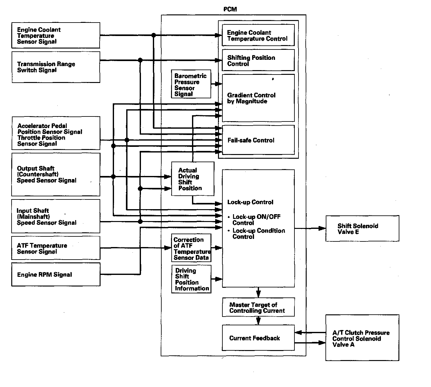
Electronic Control System
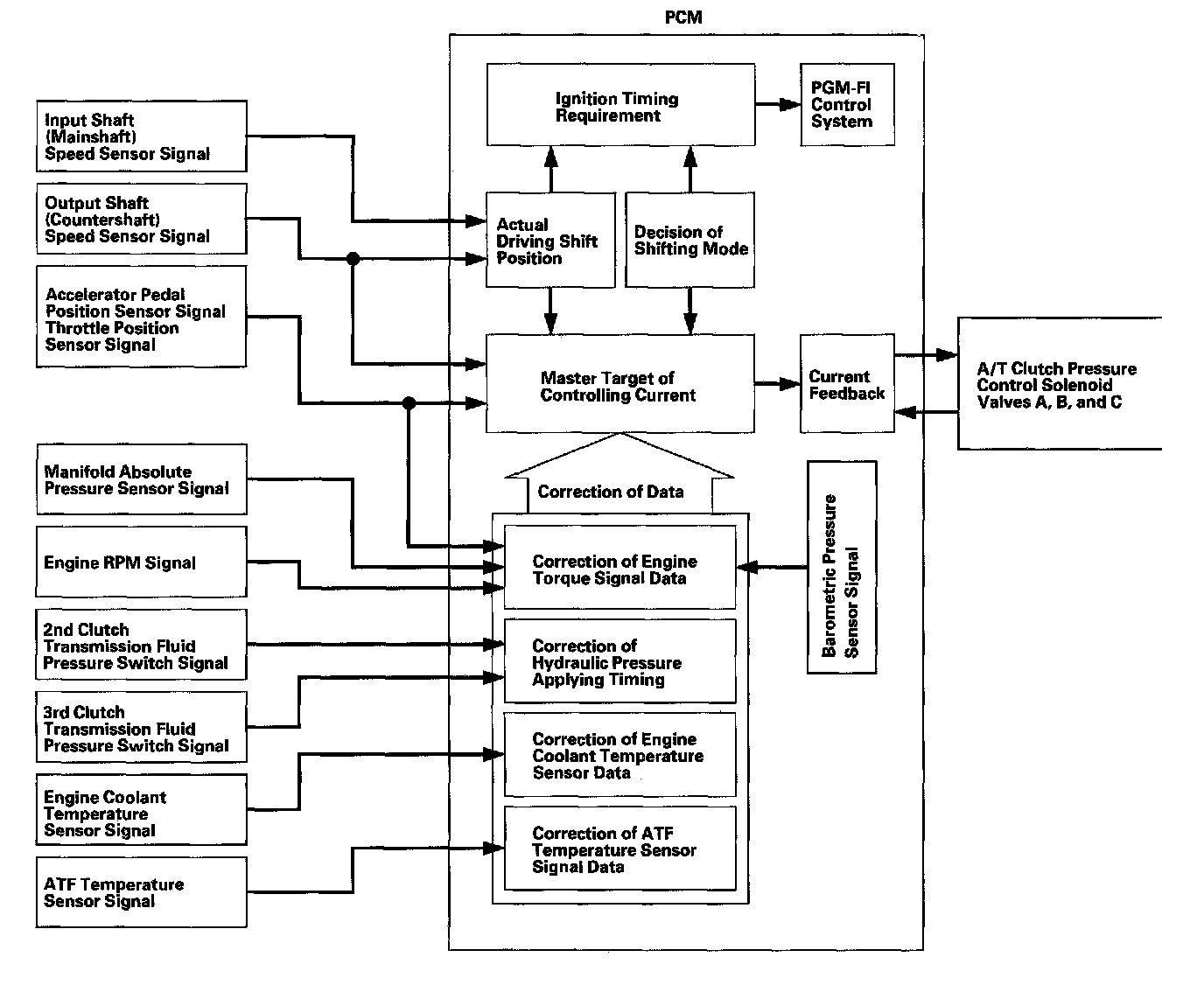
Functional Diagram
The electronic control system consists of the powertrain control module (PCM), sensors, and solenoid valves. Shifting and lock-up are electronically controlled for comfortable driving under all conditions.
The PCM receives input signals from the sensors, switches, and other control units, processes data, and outputs signals for the engine control system and A/T control system. The A/T control system includes shift control, grade logic control, clutch pressure control, and lock-up control.
The PCM actuates the shift solenoid valves and the A/T clutch pressure control solenoid valves to control shifting transmission gears and torque converter.
Shift Control
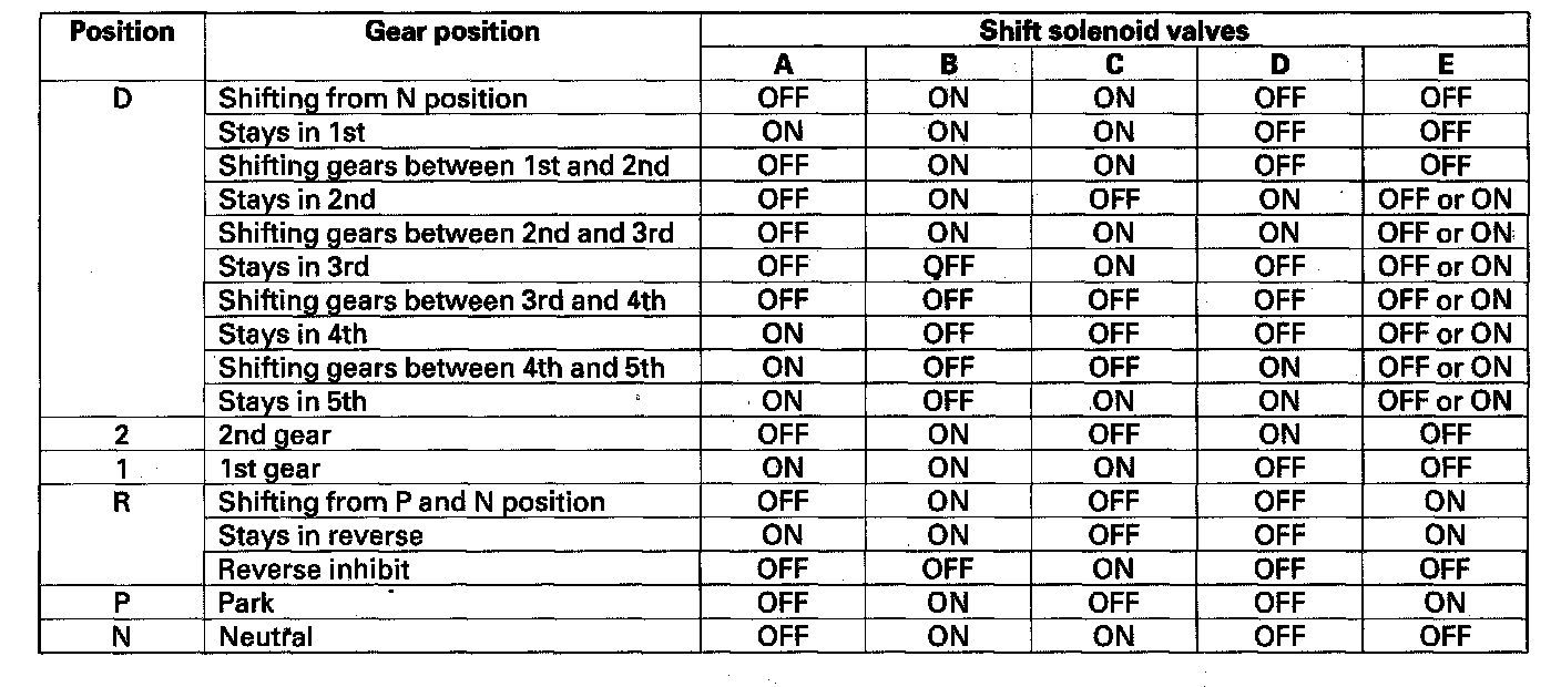
The PCM instantly determines which gear should be selected by various signals sent from sensors and switches, and it actuates the shift solenoid valves A, B, C, D, and E to control shifting transmission gears.
Shift solenoid valves are a normally closed type. Shift solenoid valve opens the port of shift solenoid valve pressure leading to shift valves while shift solenoid valve is turned ON by the PCM, and closes the port when shift solenoid valve is OFF.
The combination of driving signals to shift solenoid valves A, B, C, D, and E are shown in the table.
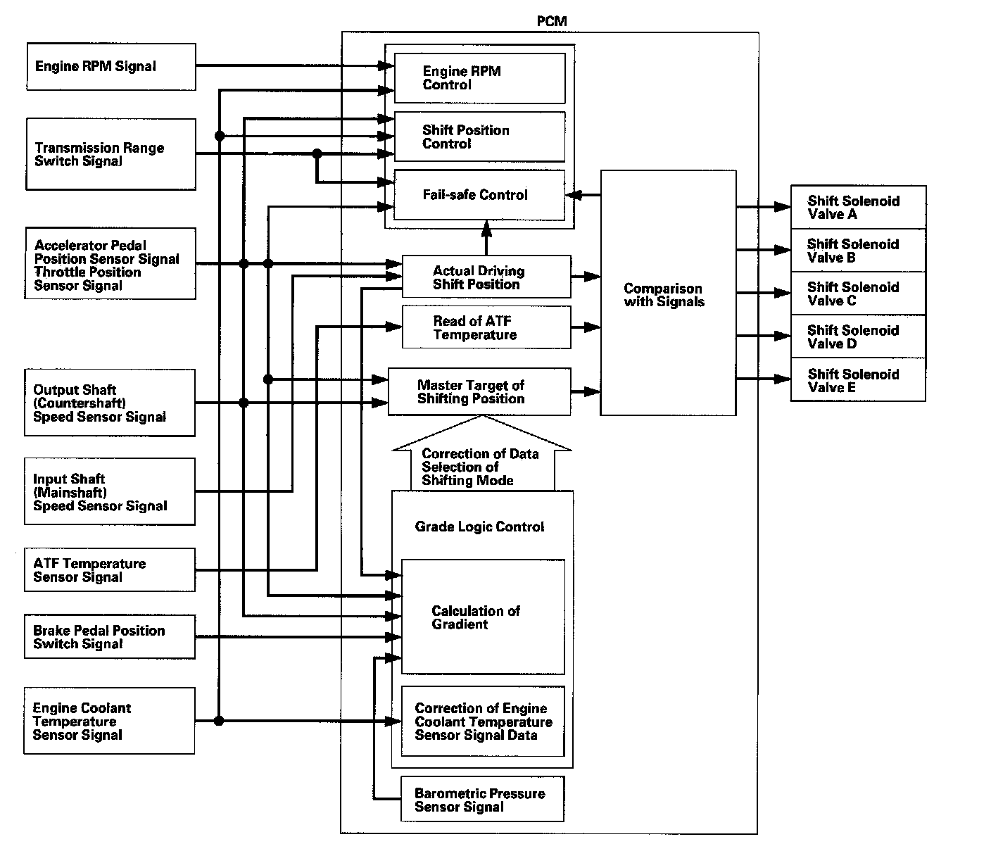
Shift Control - Grade Logic Control
The grade logic control system has been adopted to control shifting in the D position. The PCM compares actual driving conditions with programmed driving conditions, based on signals from the accelerator pedal position sensor, the throttle position sensor, the engine coolant temperature sensor, the barometric pressure sensor, the brake pedal position switch signal, and the shift lever position signal, to control shifting while the vehicle is ascending or descending a slope.
Grade Logic Control: Ascending Control
When the PCM determines that the vehicle is climbing a hill in the D position, the grade logic system extends the engagement area of 2nd, 3rd, and 4th gears to prevent the transmission from frequently shifting between 2nd and 3rd gears, between 3rd and 4th gears, and between 4th and 5th gears, so the vehicle can run smooth and have more power when needed.
Shift programs stored in the PCM between 2nd and 3rd gears, between 3rd and 4th gears, and between 4th and 5th gears, enable it to automatically select the most suitable gear according to the magnitude of a gradient.

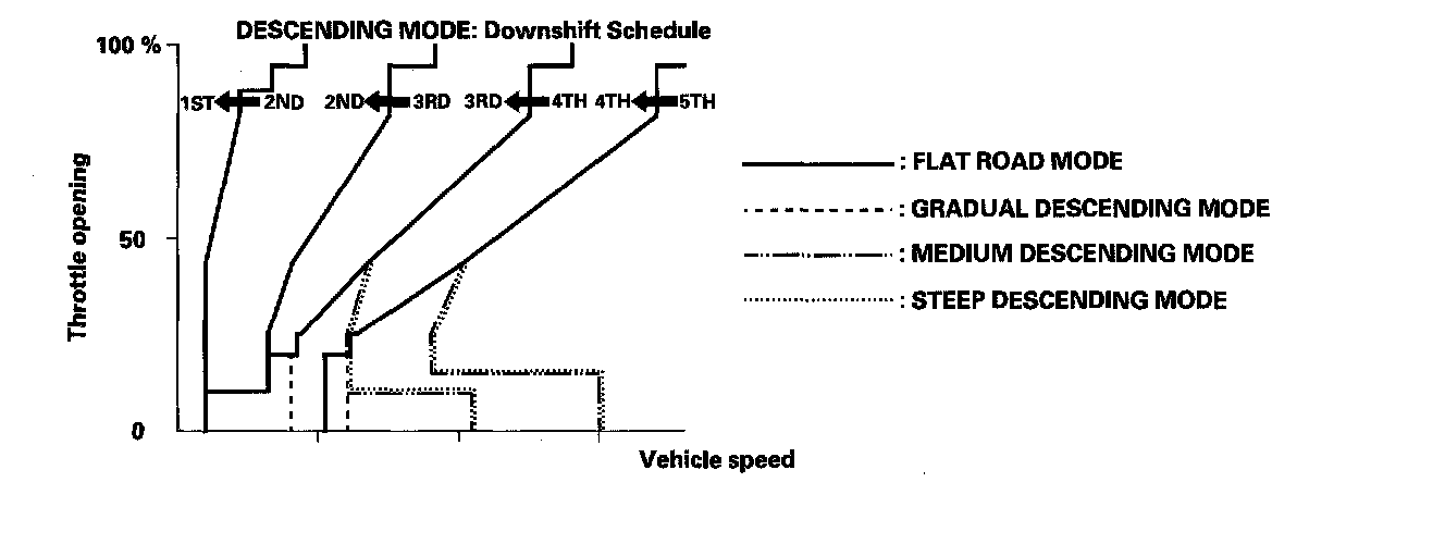
Grade Logic Control: Descending Control
When the PCM determines that the vehicle is going down a hill in the D position, the shift-up speed from 4th to 5th gear, from 3rd to 4th gear, and from 2nd to 3rd gear (when the throttle is closed) becomes faster than the set speed for flat road driving to widen the 4th gear, 3rd gear, and 2nd gear driving area. This, in combination with engine braking from the deceleration lock-up, achieves smooth driving when the vehicle is descending. There are three descending modes with different 4th gear driving areas, 3rd gear driving areas, and 2nd gear driving areas according to the magnitude of a gradient stored in the PCM. When the vehicle is in 5th gear or 4th gear, and you are decelerating when you are applying the brakes on a steep hill, the transmission will downshift to lower gear. When you accelerate, the transmission will then return to a higher gear.
Shift Control - D Position D3 Driving Mode Control
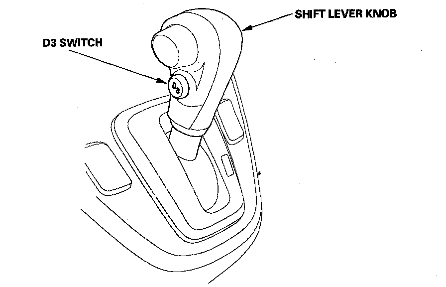
The automatic transmission is provided with the D3 driving mode in the D position. The D position has two modes; general driving mode (shifts gears automatically 1st through 5th), and the D3 driving mode (shifts gears automatically 1st through 3rd). The transmission mode switches by pushing the D3 switch on the shift lever knob in the D position.
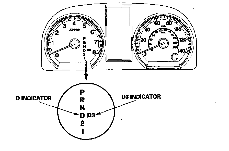
In the D3 driving mode, the D3 indicator next to the D indicator in the gauge assembly comes on. The D3 driving mode is cancelled by pushing the D3 switch, and the D3 indicator goes off. Also, the D3 driving mode is cancelled when the ignition switch is turned off. When the shift lever is moved out of the D position in the D3 driving mode, the D3 indicator goes off, but the transmission returns into D3 driving mode when returning the shift lever into the D position, and the D3 indicator comes on.
Clutch Pressure Control
The PCM actuates A/T clutch pressure control solenoid valves A, B, and C to control the clutch pressure. When shifting between gears, the clutch pressure regulated by A/T clutch pressure control solenoid valves A, B, and C engages and disengages the clutch smoothly.
The PCM receives input signals from the various sensors and switches, processes data, and outputs current to A/T clutch pressure control solenoid valves A, B, and C.
Lock-up Control
The shift solenoid valve E controls the hydraulic pressure to switch the lock-up shift valve and lock-up ON and OFF. The PCM actuates the shift solenoid valve E and the A/T clutch pressure control solenoid valve A to start lock-up. The A/T clutch pressure control solenoid valve A applies and regulates hydraulic pressure to the lock-up control valve to control the volume of the lock-up.
The lock-up mechanism operates in the D position (2nd, 3rd, 4th, and 5th), and in the D position D3 driving mode (2nd and 3rd).
PCM A/T Control System Electrical Connections:

PCM A/T Control System Inputs and Outputs (Part 1):

PCM A/T Control System Inputs and Outputs (Part 2):

PCM A/T Control System Inputs and Outputs (Part 3):
