A/T Clutch Pressure Control Solenoid Valve B Test
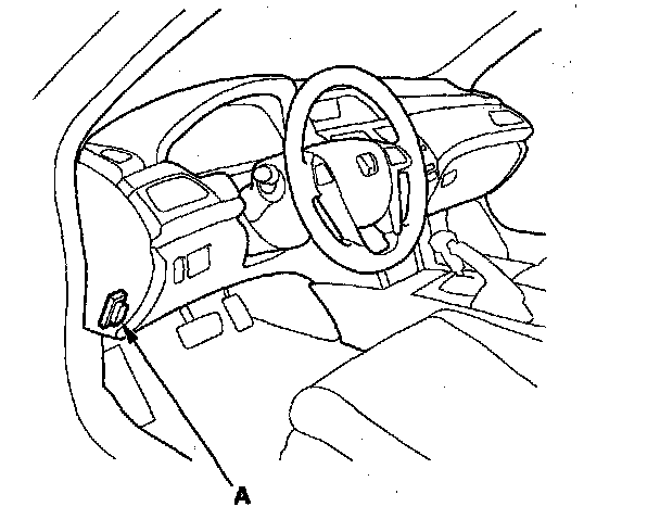
A/T Clutch Pressure Control Solenoid Valve B Test1. Connect the HDS to the DLC (A) located under the driver's side of the dashboard.
2. Turn the ignition switch to ON (II). Make sure the HDS communicates with the PCM. If it does not, go to the DLC circuit troubleshooting.
3. Select Clutch Pressure Control (Linear) Solenoid Valve B in the Miscellaneous Test Menu on the HDS.
4. Test A/T clutch pressure control solenoid valve B with the HDS.
^ If the valve tests OK, the test is complete. Disconnect the HDS.
^ If the valve does not test OK, follow the instructions on the HDS.
^ If the valve does not test OK, and the HDS does not determine the cause, go to step 5.
5. Do the battery removal procedure.
6. Loosen the two bolts located behind the battery base, and remove the two bolts securing the battery base, then remove the battery base.
7. Disconnect the A/T clutch pressure control solenoid valve B connector.
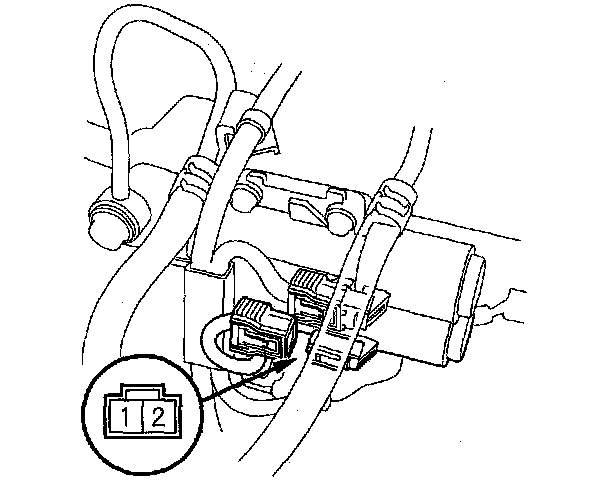
8. Measure the resistance between A/T clutch pressure control solenoid valve B connector terminals No. 1 and No. 2.
Standard: 3 - 10 ohms
^ If the resistance is within the standard, go to step 11.
^ If the resistance is out of standard, replace A/T clutch pressure control solenoid valve B.
9. Connect a jumper wire from the negative battery terminal to A/T clutch pressure control solenoid valve B connector terminal No. 2, and connect another jumper wire from the positive battery terminal to A/T clutch pressure control solenoid valve B connector terminal No. 1.
^ If a clicking sound is heard, the valve is OK. The test is complete, reconnect the connector, then go to step 19.
^ If no clicking sound is heard, go to step 10.
10. Disconnect the A/T clutch pressure control solenoid valve C connector, then remove A/T clutch pressure control solenoid valve B and C.
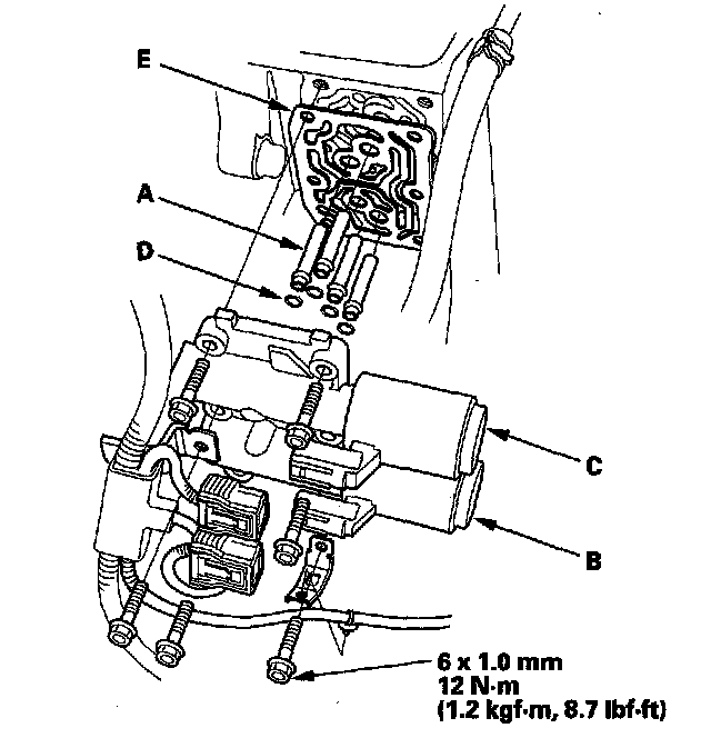
11. Remove the ATF joint pipes (A), the O-rings (D), and the gasket (E).
12. Check the fluid passage of A/T clutch pressure control solenoid valve B and C for contamination.
13. Connect a jumper wire from the negative battery terminal to A/T clutch pressure control solenoid valve B connector terminal No. 2, and connect another jumper wire from the positive battery terminal to connector terminal No. 1. Make sure A/T clutch pressure control solenoid valve B moves.
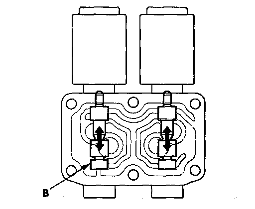
14. Disconnect one of the jumper wires, and check the valve movement at the fluid passage in the valve body mounting surface. If the valve binds or moves sluggishly, or if the solenoid valve does not operate, replace A/T clutch pressure control solenoid valve B and C.
15. Clean the mounting surface and the fluid passage of the solenoid valve body and the transmission housing.
16. Install a new gasket on the transmission housing, and install the ATF joint pipes. Install new O-rings over the ATF joint pipes.
NOTE: Be sure to install a new gasket with the blue side toward the transmission housing.
17. Install A/T clutch pressure control solenoid valve B and C.
18. Check the connectors for rust, dirt, or oil, clean or repair if necessary, then connect the connectors securely.
19. Install the battery base.
20. Do the battery installation procedure.