Shift Interlock Solenoid: Service and Repair
Shift Solenoid Valve Test, Replacement, and Shift Solenoid Wire Harness Replacement
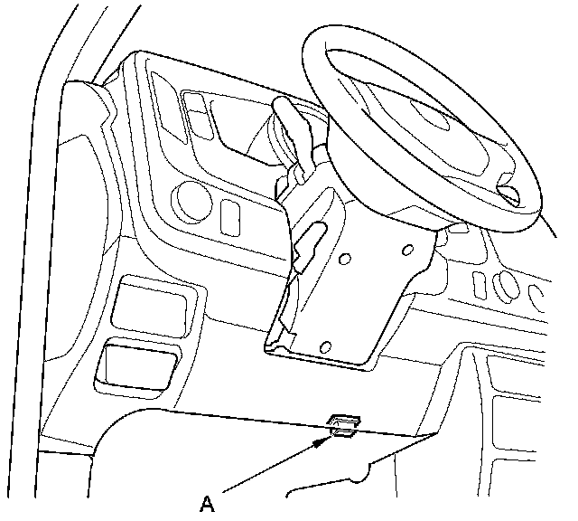
1. Connect the HDS to the DLC (A).
2. Turn the ignition switch to ON (II). Make sure the HDS communicates with the PCM. If it does not, go to the DLC circuit troubleshooting Testing and Inspection.
3. Select Shift Solenoid valves A, B, C, or D in the Miscellaneous Test Menu on the HDS.
4. Check that shift solenoid valves A, B, C, or D operate with the HDS. A clicking sound should be heard.
- If a clicking sound is heard, the valves are OK. The test is complete, disconnect the HDS.
- If no clicking sound is heard, go to step 5 and test the shift solenoid valves.
5. Do the battery removal procedure Removal and Replacement, then remove the battery tray.
6. Remove the engine cover and the air intake duct.
7. Remove the air cleaner Service and Repair.
8. Remove the air intake duct A and B Service and Repair.
9. Remove the battery base and the battery base bracket.
10. Remove the spring clip (A) and the control pin (B), then separate the shift cable end (C) from the selector control lever (D).
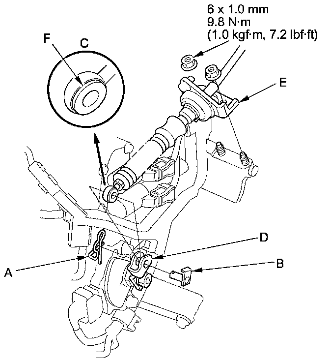
11. Remove the nuts securing the shift cable bracket (E).
12. Check the bushing (F) in the shift cable end for proper fit and wear. If the bushing is loose or worn, replace the shift cable Service and Repair.
13. Remove the bolt securing the harness cover (A).
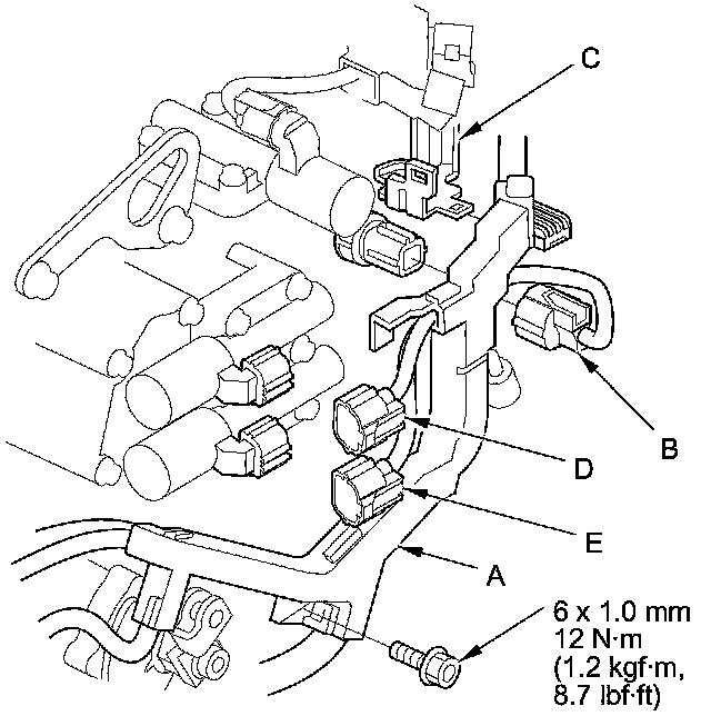
14. Disconnect 4th clutch transmission fluid pressure switch connector (B), then remove the harness cover from the harness cover bracket (C).
15. Disconnect the A/T clutch pressure control solenoid valve A connector (D), the A/T clutch pressure control solenoid valve B connector (E), the solenoid harness connector, the transmission range switch connector, the ATF temperature sensor connector, the output shaft (countershaft) speed sensor connector, the input shaft (mainshaft) speed sensor connector, and the transmission fluid pressure switch B (3rd clutch) connector.
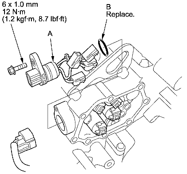
16. Remove A/T clutch pressure control solenoid valves A and B, the ATF pipes (C), and the gasket (D).
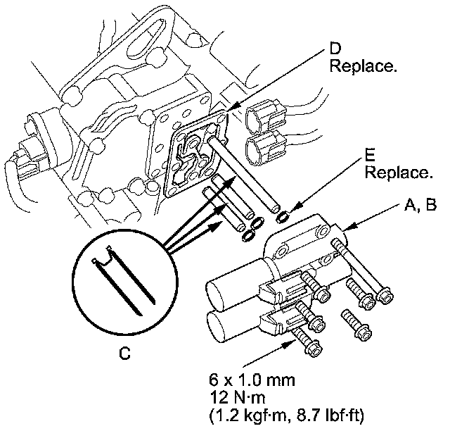
17. Replace the gasket and the O-rings (E) with new ones when installing A/T clutch pressure control solenoid valves A and B.
18. Remove the solenoid valve cover (A), the dowel pins (B), and the gasket (C).
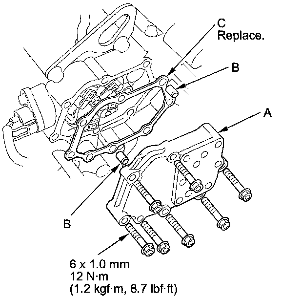
19. Replace the gasket with a new one when installing the solenoid cover.
20. Disconnect the connector from the shift solenoid valve(s) that did not click.
21. Measure the resistance of each shift solenoid valve between the connector terminal and body ground.

- If the resistance is out of standard, go to step 24 and replace the shift solenoid valve.
- If the resistance is within the standard, go to step 22 and check the shift solenoid valve for a clicking sound.
22. Connect a jumper wire from the negative battery terminal to the body ground, and connect another jumper wire from the positive battery terminal to each solenoid valve terminal individually. A clicking sound should be heard.
- If a clicking sound is heard, go to step 23 and replace the shift solenoid wire harness.
- If no clicking sound is heard, go to step 24 and replace the shift solenoid valve.
23. Remove the shift solenoid wire harness (A), and replace it. Install a new O-ring (B) on the shift solenoid wire harness, and install the shift solenoid wire harness in the transmission housing, then go to step 32.
24. Remove the necessary mounting bolts, then remove the affected solenoid valves.
NOTE: Shift solenoid valves A and C use the same mounting bolt. Shift solenoid valve C must be removed before shift solenoid valve A.
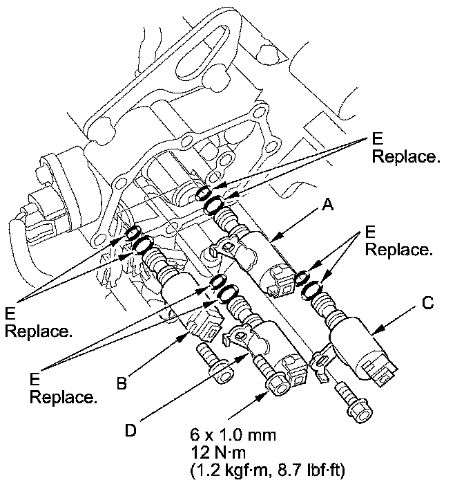
25. Install new O-rings (two O-rings per solenoid valve) (E) on each reused shift solenoid valves.
NOTE: A new solenoid valve comes with new O-rings. If you install a new solenoid valve, use the O-rings provided on it.
26. If shift solenoid valve D was replaced, install shift solenoid valve D (black connector) by holding the shift solenoid valve body; make sure the mounting bracket contacts the accumulator body.
NOTE: Do not hold the solenoid valve by the connector when installing the solenoid valve. Be sure to hold the solenoid valve body.
27. If shift solenoid valve A was replaced, install shift solenoid valve A (black connector) by holding the solenoid valve body; make sure the mounting bracket contacts the accumulator body.
NOTE: Do not install shift solenoid valve C before installing shift solenoid valve A. If shift solenoid valve C is installed before installing shift solenoid valve A, it may damage to hydraulic control system.
28. If shift solenoid valve C was replaced, install shift solenoid valve C (brown connector) by holding the shift solenoid valve body; make sure the mounting bracket contacts the bracket of shift solenoid valve A.
29. If shift solenoid valve B was replaced, install shift solenoid valve B (brown connector) by holding the shift solenoid valve body; make sure the mounting bracket contacts the accumulator body.
30. Install the shift solenoid valve mounting bolts.
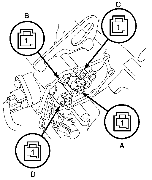
31. Connect the harness terminals to the solenoid:
- YEL wire connector to shift solenoid valve A
- RED wire connector to shift solenoid valve B
- GRN wire connector to shift solenoid valve C
- ORN wire connector to shift solenoid valve D
32. Install the shift solenoid valve cover, the dowel pins, and a new gasket.
33. Install a new solenoid valve body gasket on the solenoid valve cover, and install the ATF pipes with their filter side into the transmission housing. Install new O-rings over the ATF pipes.
34. Install A/T clutch pressure control solenoid valves A and B.
35. Install the harness cover on the harness cover bracket and secure it with the bolt.
36. Check the connectors for rust, dirt, or oil, and clean or repair if necessary, then connect the connectors securely.
37. Apply molybdenum grease to the hole in the bushing in the shift cable end, then install the shift cable bracket with the nuts.
38. Attach the shift cable end to the selector control lever, then insert the control pin into the selector control lever hole through the shift cable end, and secure the control pin with the spring clip.
39. Install the battery base bracket and the battery base.
40. Install the air intake duct A and B Service and Repair.
41. Install the air cleaner Service and Repair.
42. Install the air intake duct and the engine cover.
43. Install the battery tray, then do the battery installation procedure Removal and Replacement.