Recall - SRS Terminal Installation Re-Issue
Group01 - RECALL BULLETINS
Number
97-01-003
Date
04-1997
Model
Elantra 1994-1995
Subject
SRS SYSTEM TERMINAL HOLDER INSTALLATION CAMPAIGN (26)
THE TSB, PREVIOUSLY ISSUED AS 95-01-004, HAS BEEN RE-ISSUED IN CONJUNCTION WITH THE SECOND CUSTOMER NOTICE LETTER
DESCRIPTION:
This bulletin describes the steps necessary to inspect or install the terminal holder of connector M84.
SERVICE PROCEDURE:
1. Turn the ignition switch to the ON position. The air bag warning indicator lamp should flash for six seconds and then turn off Note if the light remains on continuously. Turn the ignition key to the OFF position and remove the key from the ignition switch. Disconnect the negative battery cable and wait 30 seconds for the SRS system back up power source to discharge before proceeding to step 2.
NOTE
Always record the customer's radio station settings prior to disconnecting the battery.
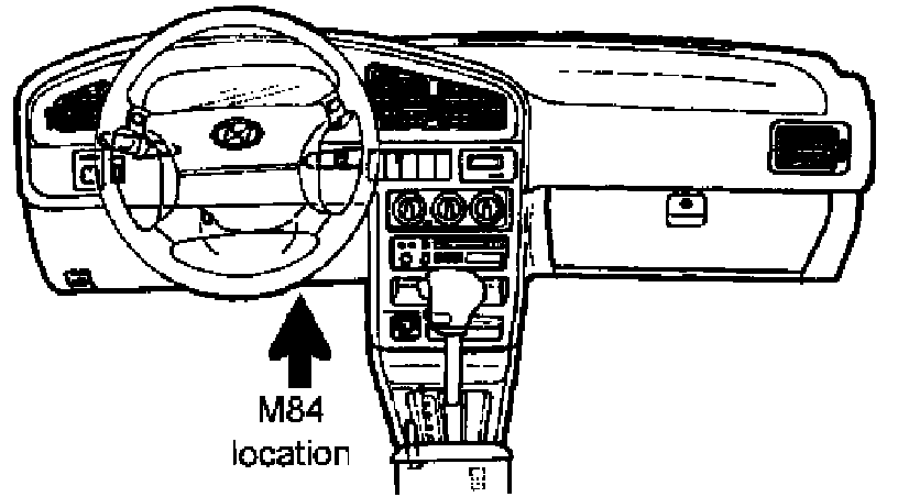
2. Locate connector M84 behind the lower crash pad. This connector connects the yellow SRS wiring harness to the clock spring assembly wiring harness. See illustration.
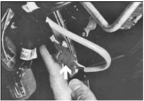
3. Inspect the clock spring harness side of connector M84 to determine if a terminal holder has been installed. See illustration.
If a terminal holder has been installed, proceed to Step 4.
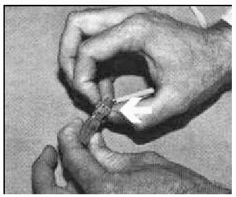
If a terminal holder has not been installed, lift the green retainer and unplug the connector.
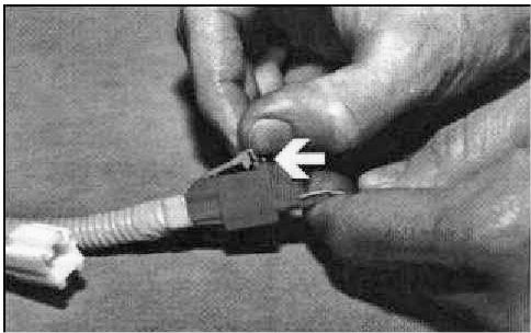
Install the terminal holder into the clock spring's M84 connector housing. The terminal holder should snap securely into the connector body. Reconnect the two terminals and secure the green retainer.
4. Reconnect the negative battery cable to the battery. If the SRS warning indicator lamp was illuminated continuously when the ignition switch was in the ON position prior to installation of the terminal holder, connect the scan tool to the vehicle's diagnostic connector to read the diagnostic code stored in the SRS control module.
If a Code 3 or 53 is indicated, clear the diagnostic code using the scan tool. If codes other than Code 3/53 are indicated, refer to the Shop Manual for system diagnostic and repair procedures.

5. Place a punch mark over the 15th digit of the VIN plate on the driver's door.
6. Re-enter the customer's pre-set radio stations and set the clock.
EFFECTIVE PRODUCTION DATE: JUNE 18, 1994 through OCTOBER 31, 1994
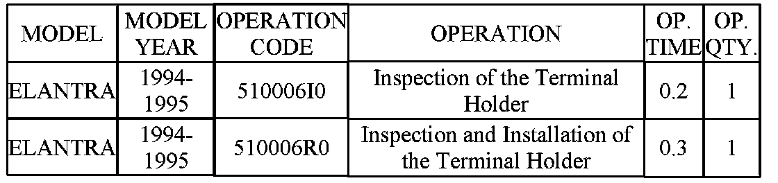
CAMPAIGN CLAIM INFORMATION
SUBMIT CLAIMS FOR THE ABOVE CAMPAIGN OPERATION CODES USING THE CAMPAIGN CLAIM SCREEN.

PARTS INFORMATION