Crankshaft: Testing and Inspection
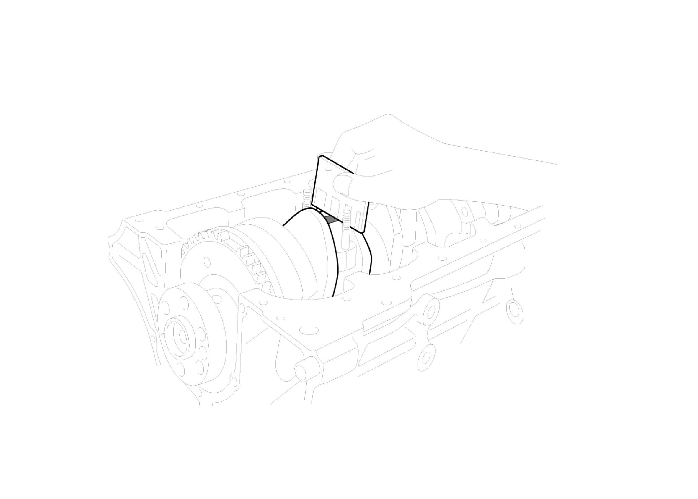
CONNECTING ROD AND CRANKSHAFT1. Check the connecting rod end play. Using feeler gauge, measure the end play while moving the connecting rod back and forth.
End play
Standard: 0.1 - 0.25 mm (0.0039 - 0.0098 in)
Maximum: 0.4 mm (0.0157 in)

^ If out-of-tolerance, install a new connecting rod.
^ If still out-of-tolerance, replace the crankshaft.
2. Check the connecting rod bearing oil clearance.
A. Check the match marks on the connecting rod and cap are aligned to ensure correct reassembly.
B. Remove the 2 connecting rod cap nuts.
C. Remove the connecting rod cap and lower bearing.
D. Clean the crankshaft pin journal and bearing.
E. Place a plastigage across the crankshaft pin journal.
F. Reinstall the lower bearing and cap, and tighten the nuts.
Tightening torque: 31.4 - 34.3 N.m (3.2 - 3.5 kgf.m, 23.1 - 25.3 lb-ft)
NOTE: Do not turn the crankshaft.
G. Remove the 2 nuts, connecting rod cap and lower bearing.
H. Measure the plastigage at its widest point.
Standard oil clearance 0.018 - 0.036 mm (0.0007 - 0.0014 in)
I. If the plastigage measures too wide or too narrow, remove the upper and lower bearing and then install a new bearings with the same color mark. Recheck the oil clearance.
CAUTION: Do not file, shim, of scrape the bearings or the caps to adjust clearance.
J. If the plastigage shows the clearance is still incorrect, try the next larger or smaller bearing. Recheck the oil clearance.
NOTE: If the proper clearance cannot be obtained by using the appropriate larger or smaller bearings, replace the crankshaft and start over.
CAUTION: If the marks are indecipherable because of an accumulation of dirt and dust, do not scrub them with a wire brush or scraper. Clean them only with solvent or detergent.
Connecting rod mark location:

Identification of connecting rod:

Crankshaft pin journal mark location:


Connecting rod bearing mark location:

Identification of connecting rod bearing:

K. Select the bearing by using selection table.
Connecting rod bearing selection table:

3. Check the connecting rods.
A. When reinstalling, make sure that cylinder numbers put on the connecting rod and cap at disassembly match. When a new connecting rod is installed, make sure that the notches for holding the bearing in place are on the same side.
B. Replace the connecting rod if it is damaged on the thrust faces at either end. Also if step wear or a severely rough surface of the inside diameter of the small end is apparent, the rod must be replaced as well.
C. Using a connecting rod aligning tool, check the rod for bend and twist. If the measured value is close to the repair limit, correct the rod by a press. Any connecting rod that has been severely bent or distorted should be replaced.
Allowable bend of connecting rod: 0.05 mm / 100 mm (0.0020 in / 3.94 in ) or less
Allowable twist of connecting rod: 0.1 mm / 100 mm (0.0039 in / 3.94 in) or less
4. Check the crankshaft bearing oil clearance.
A. To check main bearing-to-journal oil clearance, remove the main bearing caps and lower bearings.
B. Clean each main journal and lower bearing with a clean shop towel.
C. Place one strip of plastigage across each main journal.
D. Reinstall the lower bearings and caps, then tighten the bolts.
Tightening torque: 53.9 - 58.8 N.m (5.5 6.0 kgf.m, 39.8 - 43.4 lb-ft)
NOTE: Do not turn the crankshaft.
E. Remove the cap and lower bearing again, and measure the widest part of the plastigage.
Standard oil clearance:
No.1, 2, 4, 5: 0.022 - 0.040 mm (0.0009 - 0.0016 in)

F. If the plastigage measures too wide or too narrow, remove the upper and lower bearing and then install a new bearings with the same color mark. Recheck the oil clearance.
CAUTION: Do not file, shim, or scrape the bearings or the cap to adjust clearance.
G. If the plastigage shows the clearance is still incorrect, try the next larger or smaller bearing. Recheck the oil clearance.
NOTE: If the proper clearance cannot be obtained by using the appropriate larger or smaller bearings, replace the crankshaft and start over.
CAUTION: If the marks are indecipherable because of an accumulation of dirt and dust, do not scrub them with a wire brush or scraper. Clean them only with solvent or detergent. Cylinder block crankshaft journal bore mark location
Letters have been stamped on the end of the block as a mark for the size of each of the 5 main journal bores. Use them, and the numbers or letters stamped on the crank (marks for main journal size), to choose the correct bearings.

Identification of cylinder block crankshaft journal bore:

Crankshaft main journal mark location:

Identification of crankshaft main journal:

Crankshaft main bearing mark location:

Identification of crankshaft main bearing:

Identification of crankshaft main bearing:

H. Select the bearing by using selection table.
Crankshaft main bearing selection table:

5. Check the crankshaft end play. Using a dial indicator, measure the thrust clearance while prying the crankshaft back and forth with a screwdriver.
End play
Standard: 0.05 - 0.175 mm (0.0020 - 0.0069 in)
Limit: 0.20 mm (0.0079 in)

If the end play is greater than maximum, replace the center bearing.
6. Inspect the crankshaft main journals and pin journals. Using a micrometer, measure the diameter of each main journal and pin journal.
Main journal diameter: 49.950 - 49.968 mm (1.9665 - 1.9672 in)
Pin journal diameter: 44.954 - 44.972 mm (1.7698 - 1.7705 in)
