Part 1
Removal
CAUTION:
- Use fender covers to avoid damaging painted surfaces.
- To avoid damaging the cylinder head, wait until the engine coolant temperature drops below normal temperature (20°C [68°F]) before removing it.
- When handling a metal gasket, take care not to fold the gasket or damage the contact surface of the gasket.
- To avoid damage, unplug the wiring connectors carefully while holding the connector portion.
NOTE:
- Mark all wiring and hoses to avoid misconnection.
- Turn the crankshaft pulley so that the No. 1 piston is at top dead center.
1. Remove the intake and exhaust manifolds.
2. Remove the timing chain.
3. Disconnect the heater hoses and then remove the water temperature control assembly.
4. Remove the injector & rail assembly.
5. Remove the fuel pump bracket (A).

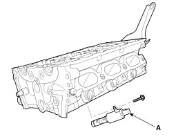
6. Remove the LH/RH exhaust camshaft OCV (A).
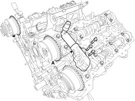

7. Remove the LH/RH camshaft bearing cap (A) and thrust bearing cap (B).


8. Remove the LH/RH camshaft assembly (A).


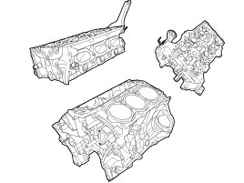
9. Remove the cylinder head.
(1) Remove the RH cylinder head rear bolts (A).

(2) Uniformly loosen and remove the cylinder head bolts, in several passes, in the sequence shown.

CAUTION:
Head warpage or cracking could result from removing bolts in an incorrect order.
(3) Lift the cylinder head from the dowels on the cylinder block and place the cylinder head on wooden blocks on a bench.
CAUTION:
Be careful not to damage the contact surfaces of the cylinder head and cylinder block.
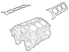
(4) Remove the LH/RH cylinder head gaskets.
Disassembly
NOTE:
Identify MLA, valves and valve springs as they are removed so that each item can be reinstalled in its original position.
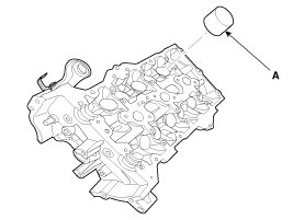
1. Remove the MLAs(A).
2. Remove the valves.
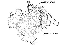
(1) Using the SST(09222-3K000, 09222-3K100), compress the valve spring and remove retainer lock.
(2) Remove the spring retainer.
(3) Remove the valve spring.
(4) Remove the valve.
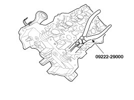
(5) Using the SST(09222-29000), remove the valve stem seal.
NOTE:
Do not reuse old valve stem seals.
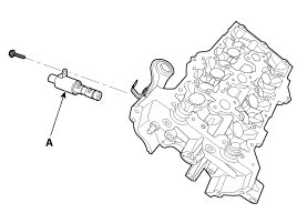
3. Remove the LH/RH intake OCV(A).
Inspection
Cylinder Head
1. Inspect for flatness.
Using a precision straight edge and feeler gauge, measure the surface contacting cylinder block and the manifolds for warpage.
Flatness of cylinder head gasket surface
Standard : Less than 0.05mm(0.002in.)
[Less than 0.02mm(0.0008in.)/150x150]
Flatness of manifold gasket surface
Standard : Less than 0.03mm(0.001in)/110x110

2. Inspect for cracks.
Check the combustion chamber, intake ports, exhaust ports and cylinder block surface for cracks. If cracked, replace the cylinder head.
Valve And Valve Spring
1. Inspect valve stems and valve guides.
(1) Using a caliper gauge, measure the inside diameter of the valve guide.
Valve guide I.D.
Intake / Exhaust : 5.500 - 5.512mm (0.216 - 0.217in.)

(2) Using a micrometer, measure the diameter of the valve stem.
Valve stem O.D.
Intake : 5.465 - 5.480mm (0.2151 - 0.2157in.)
Exhaust : 5.458 - 5.470mm (0.2149 - 0.2153in.)

(3) Subtract the valve stem diameter measurement from the valve guide inside diameter measurement.
Valve stem-to-guide clearance
[Standard]
Intake : 0.020 - 0.047mm (0.0008 - 0.0018in.)
Exhaust : 0.030 - 0.054mm (0.0012 - 0.0021in.)
[Limit]
Intake : 0.07mm (0.0027in.)
Exhaust : 0.09mm (0.0035in.)
2. Inspect valves.
(1) Check the valve is ground to the correct valve face angle.
(2) Check that the surface of the valve for wear.
If the valve face is worn, replace the valve.
(3) Check the valve head margin thickness.
If the margin thickness is less than minimum, replace the valve.
Margin
[Standard]
Intake : 1.56 - 1.86mm (0.06142 - 0.07323in.)
Exhaust : 1.73 - 2.03mm (0.06811 - 0.07992in.)

(4) Check the valve length.
Length
Intake : 105.27mm (4.1445in)
Exhaust : 105.50mm (4.1535in)
(5) Check the surface of the valve stem tip for wear.
If the valve stem tip is worn, replace the valve.
3. Inspect valve seats
Check the valve seat for evidence of overheating and improper contact with the valve face.
If the valve seat is worn, replace cylinder head.
Before reconditioning the seat, check the valve guide for wear. If the valve guide is worn, replace cylinder head. Recondition the valve seat with a valve seat grinder or cutter. The valve seat contact width should be within specifications and centered on the valve face.
4. Inspect valve springs.
(1) Using a steel square, measure the out-of-square of the valve spring.
(2) Using vernier calipers, measure the free length of the valve spring.
Valve spring
[Standard]
Free height : 45.5mm (1.7913in.)
Out-of-square : 1.5°
