Diagnosis Procedure
VP SIGNAL CIRCUIT (FRONT DISPLAY UNIT TO AV CONTROL UNIT)
Diagnosis Procedure
1.CHECK CONTINUITY VERTICAL SYNCHRONIZING (VP) SIGNAL CIRCUIT
1. Turn ignition switch OFF.
2. Disconnect front display unit connector and AV control unit connector.
3. Check continuity between front display unit harness connector terminal 20 and AV control unit harness connector terminal 101.
20 - 101 : Continuity should exist.
4. Check continuity between front display unit harness connector terminal 20 and ground.
20 - Ground : Continuity should not exist.
Is the inspection result normal?
YES - GO TO 2.
NO - Repair harness or connector.
2.CHECK VERTICAL SYNCHRONIZING (VP) SIGNAL
1. Connect front display unit connector and AV control unit connector.
2. Turn ignition switch ON.
3. Check signal between front display unit harness connector terminal 20 and ground.
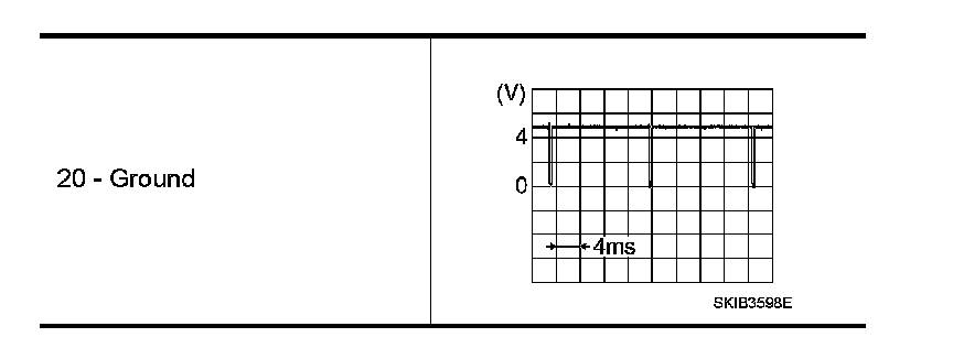
Is the inspection result normal?
YES - Replace AV control unit.
NO - Replace front display unit.