Intake Sensor Circuit
TROUBLE DIAGNOSIS
Intake Sensor Circuit
COMPONENT DESCRIPTION
Intake Sensor

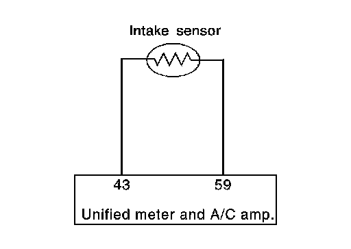
The intake sensor is located on the evaporator assembly. It converts temperature of air after it passes through the evaporator into a resistance value which is then input to the unified meter and A/C amp.
Intake Sensor Circuit
DIAGNOSIS PROCEDURE FOR INTAKE SENSOR
SYMPTOM: Intake sensor circuit is open or shorted. (24 or -24 is indicated on unified meter and A/C amp. as a result of performing self-diagnosis STEP-2.)
1.CHECK VOLTAGE BETWEEN INTAKE SENSOR AND GROUND
1. Disconnect intake sensor connector.
2. Turn ignition switch ON.
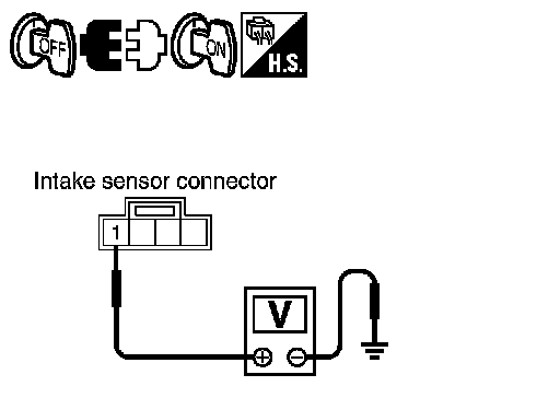
3. Check voltage between intake sensor harness connector M82 terminal 1 and ground.
1 - Ground: Approx. 5 V
OK or NG
OK - GO TO 2.
NG - GO TO 4.
2.CHECK CIRCUIT CONTINUITY BETWEEN INTAKE SENSOR AND UNIFIED METER AND A/C AMP.
1. Turn ignition switch OFF.
2. Disconnect unified meter and A/C amp. connector.
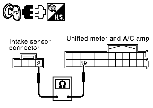
3. Check continuity between intake sensor harness connector M82 terminal 2 and unified meter and A/C amp. harness connector
M65 terminal 59.
2 - 59: Continuity should exist.
OK or NG
OK - GO TO 3.
NG - Repair harness or connector.
3.CHECK INTAKE SENSOR
Refer to "COMPONENT INSPECTION (Intake Sensor)".
OK or NG
OK - 1. Replace unified meter and A/C amp.
2. Go to self-diagnosis Self-Diagnosis Function and perform self-diagnosis STEP-2.
Confirm that code No. 20 is displayed.
NG - 1. Replace intake sensor.
2. Go to self-diagnosis Self-Diagnosis Function and perform self-diagnosis STEP-2.
Confirm that code No. 20 is displayed.
4.CHECK CIRCUIT CONTINUITY BETWEEN INTAKE SENSOR AND UNIFIED METER AND A/C AMP.
1. Turn ignition switch OFF.
2. Disconnect unified meter and A/C amp. connector.
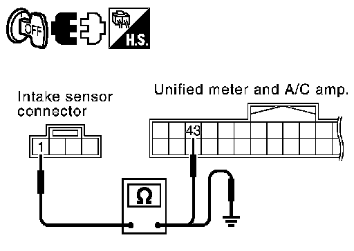
3. Check continuity between intake sensor harness connector M82 terminal 1 and unified meter and A/C amp. harness connector
M65 terminal 43.
1 - 43: Continuity should exist.
4. Check continuity between intake sensor harness connector M82 terminal 1 and ground.
1 - Ground: Continuity should not exist.
OK or NG
OK - 1. Replace unified meter and A/C amp.
2. Go to self-diagnosis Self-Diagnosis Function and perform self-diagnosis STEP-2.
Confirm that code No. 20 is displayed.
NG - Repair harness or connector.
COMPONENT INSPECTION
Intake Sensor
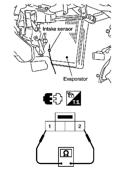
After disconnecting intake sensor connector M82, measure resistance between terminals 1 and 2 at sensor side. Refer to the table below.
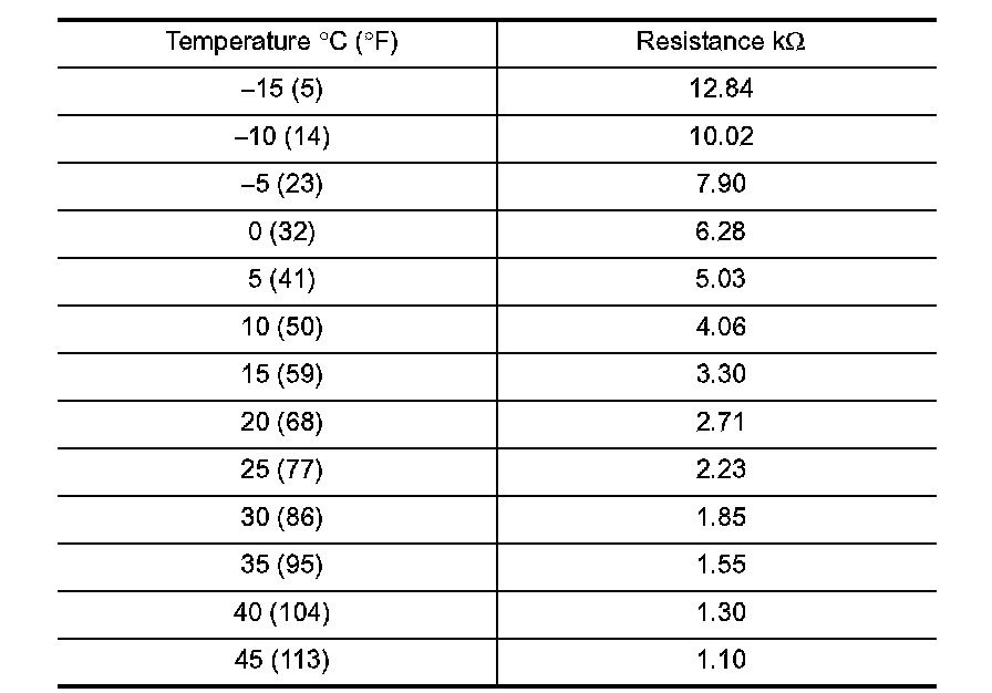
If NG, replace intake sensor.