Front Propeller Shaft
Front Propeller Shaft and Associated Parts

Removal
1. Jack up the vehicle and support it on the chassis stands.
2. Gear shift lever should be placed in neutral position and parking brake released.


3. Remove the exhaust and transfer protectors.
Note: Apply alignment marks on the flange at the front propeller shaft both front and rear side.
4. Remove bolt, nut and washer (Front axle side).
5. Remove bolt, nut and washer (Transfer side).

6. Remove front propeller shaft.
Note: If equipped with torque on demand (TOD), installing or earring for front propeller shaft, be sure to wind a piece of cloth round the part of the boot with which fittings may interfere so that the boot can be protected. The boot may be damaged if bending force is applied to the constant velocity joint of the shaft.
Installation
Note: Never install the shaft assembly backwards. Completely remove the black paint from the connecting surface of flange coupling on each end of propeller shaft. Clean so that no foreign matter will be caught in between.
1. Align the mark, which was applied at removal. Install front propeller shaft and tighten the bolts to the specified torque.
Torque: 63 Nm (46 ft. lbs.)
2. Install the exhaust and transfer protectors.

3. After installing the propeller shaft, be sure to apply black paint (1) to exposed area (other than connecting surface) of the entire surface of flange coupling.
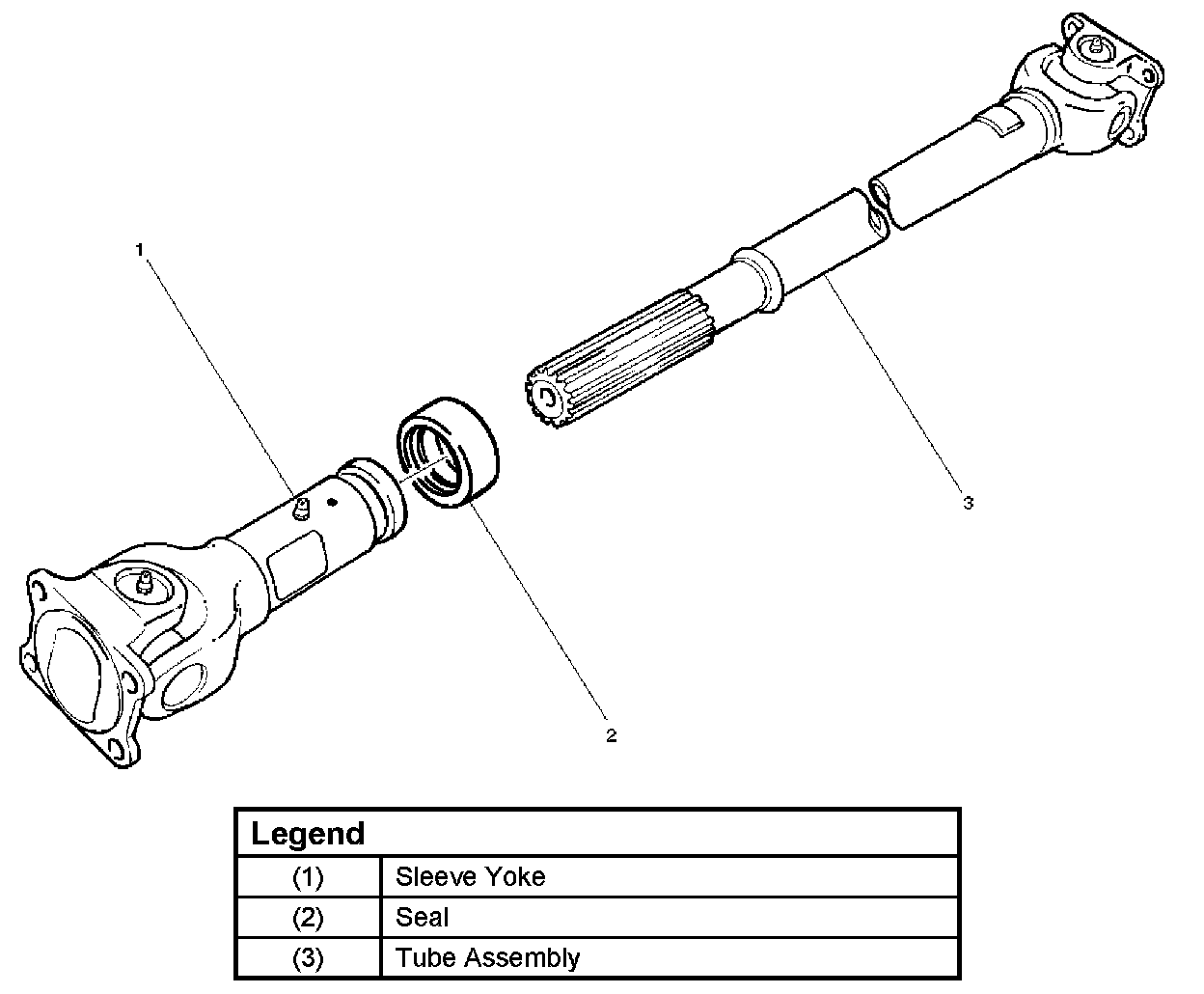
Disassembly (Except TOD 4X4)

1. Apply alignment marks (1) on the sleeve yoke and tube assembly, then remove sleeve yoke.
2. Remove seal.
3. Remove tube assembly.
Universal Joint


Disassembly

1. Apply alignment marks (1) on the yokes of the universal joint, then remove snap ring.

2. Tap out the needle roller bearing by gently striking the shoulder of the yoke, using a mallet or a copper hammer.
3. Make sure of proper position for reinstallation by applying setting marks, then remove spider.
Inspection and Repair
Make necessary correction or parts replacement if wear, damage, corrosion or any other abnormal condition is found through inspection.
Note: When any part of the journal assembly (spider, needle roller bearing) requires replacement, be sure to replace the entire assembly.
Check the following parts for wear, damage, noise or any other abnormal conditions:
1. Spider
2. Needle roller bearing
3. Yoke
4. Flange
5. Constant velocity joint
Outside Diameter of Spider Pin

Standard: 17.00 mm (0.669 inch)
Limit: 16.90 mm (0.665 inch)
Propeller Shaft Run-out

Support the ends of the propeller shaft on V-blocks (2) and check for run- out by holding the probe of a dial indicator (1) in contact with the center part of the shaft. If the amount of run-out is beyond the standard value for assembly, correct with a bench press or replace the shaft with a new propeller shaft assembly.
Standard: 0.3 mm (0.012 inch)
Limit: 0.5 mm (0.02 inch)
Play in Splines in Normal Direction of Rotation

Check the amount of play between the sleeve yoke (1) and the propeller shaft spline (2) in the direction of rotation, using a pointed feeler gauge.
Standard: 0.073 - 0.156 mm (0.003 - 0.006 inch)
Limit: 0.3 mm (0.012 inch)
Play in Universal Joint

Limit: Less than 0.1 mm (0.004 inch)
Constant Velocity Joint
Note: LJ and BJ constant velocity joints are unremovable types. Check the joint for play and the boot for damage, wear, and leak of grease. If abnormality is found, replace propeller shaft as a assembly.
Play in Constant Velocity Joint


Fix the shaft in a vise thorough pieces of wood, and try to move the joint vertically, right and left, and back and forth to make sure of smooth motions and no remarkable play.
Boot of Constant Velocity Joint


Check the boot (2) for crack, damage and grease leak, and the boot band (1) for loosening and damage. Check the both sides of the joint and make sure that there is no leak of grease from the cover press-in parts (3).
Front Axle Flange Run-out

1. Set a dial gage at right angle near the outer circumference of the flange face and check the run-out of the flange face.
Limit: 0.15 mm (0.006 inch)

2. Set a dial gage at right angle near the inner circumference and check the run-out of the flange.
Limit: 0.15 mm (0.006 inch)

3. If vibration is felt during the 4H AUTO drive, disconnect the propeller shaft at the front axle.
Reinstall the propeller shaft at 60°, 120°, 180°, 240°, and 300° and conduct test drive in each position and check if there is vibration.
Universal Joint Reassembly
1. Install spider to flange yoke. Be sure to install the spider by aligning the setting marks made during disassembly.

2. Apply a molybdenum- disulfide grease or a multi- purpose type grease NLGI No. 2 to inside of the bearing cap.
Grease Amount: Approximately 1.2 g (0.042 oz)

3. Using either a mallet (or copper hammer) or a press, install the needle roller bearing into the yoke so that the snap ring can be installed in its groove.
Caution: The needle roller bearing cannot be installed smoothly if it is set at an incorrect angle with the flange and excessive hammering will damage the needle roller bearing.
4. Align setting marks (1) and join the yokes.
5. Install snap ring.
Note: Discard used snap rings and install new ones.
When the bearing cap is in position, select and attach a snap ring of suitable thickness so that the end play of the spider pin is held within 0.1 mm (0.004 inch).
Snap ring thickness and Identification color
1.5 mm (0.059 inch); Blue
1.53 mm (0.060 inch); White
1.59 mm (0.063 inch); Yellow
1.62 mm (0.064 inch); Green
1.68 mm (0.066 inch); Not colored
Note: Be sure to use snap rings of the same thickness on both sides.
Reassembly (Except TOD 4X4)
1. Discard used seal and install new one.
2. Align the alignment marks and install tube assembly to sleeve yoke.