Air Conditioning
Air Conditioning

The air conditioning (A/C) system is a clutch cycling, thermostatic expansion valve type. The system components are:
- A/C Compressor
- Compressor clutch
- Condenser core
- Evaporator core
- Thermostatic expansion valve
- Desiccant bag
- Connecting refrigerant lines
The refrigeration system operation is controlled by the:
- Thermostatic expansion valve.
- Evaporator discharge temperature sensor.
- A/C Compressor relief valve.
- Pressure cut off switch.
- Engine control module (ECM)
- Climate control module
The refrigerant system incorporates a variable capacity A/C compressor. The A/C compressor clutch engagement is controlled by the ECM.
The DATC module monitors the evaporator discharge temperature sensor and communicates with the ECM to control clutch cycling. The DATC also monitors the ambient air temperature and disables A/C operation when the ambient air temperature is below 0 degree C (30 degree F).
The pressure switch is located in the A/C compressor discharge line and communicates with the ECM. If high or low refrigerant pressures are experienced, the ECM will interrupt A/C compressor operation.
The pressure relief valve is installed in the A/C compressor manifold and tube assembly and protects the system from excessively high refrigerant pressure.
The thermostatic expansion valve, which is mounted to the evaporator core supply and return lines, contains an adjustable orifice which provides the restriction that separates the high and low pressure liquid phases in the refrigerant system.
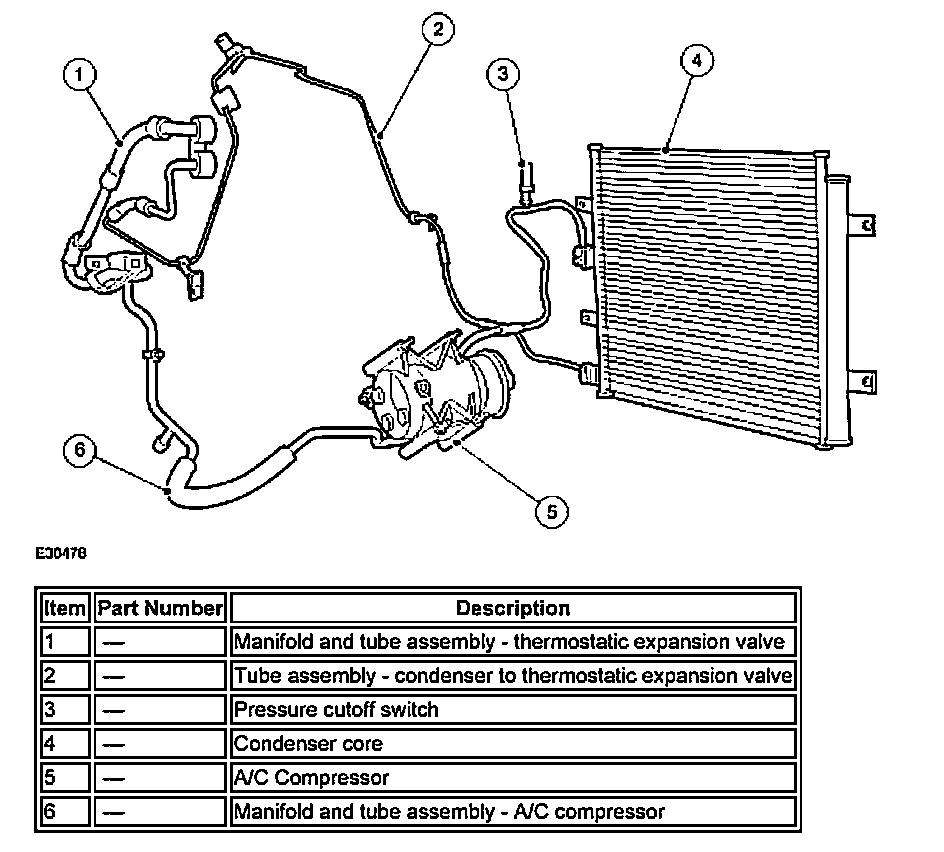
A/C Compressor and Clutch Assembly
NOTE: The internal A/C compressor components are not serviced separately. The A/C scroll compressor is serviced only as an assembly.
The A/C compressor has the following characteristics:
- A variable capacity function controlled by a suction pressure device.
- Vehicles fitted with 4.2L engine a displacement of 105cc.
- Vehicles fitted with 2.5L and 3.0L engine a displacement of 90cc.
- A fixed and orbiting scroll to provide refrigerant compression.
- A non-serviceable shaft seal.

The magnetic A/C clutch has the following characteristics:
- It drives the compressor shaft.
- When battery positive voltage is applied to the A/C clutch field coil, the clutch disc and hub assembly is drawn toward the A/C clutch pulley.
- The magnetic force locks the clutch disc and hub assembly and the A/C clutch pulley together as one unit, causing the compressor shaft to rotate.
- When battery positive voltage is removed from the A/C clutch field coil, springs in the clutch disc and hub assembly move the clutch disc away from the A/C clutch pulley.
A/C Compressor Pressure Relief Valve
An A/C compressor pressure relief valve is incorporated in the compressor A/C manifold and tube to:
- relieve unusually high refrigerant system discharge pressure buildups.
- prevent damage to the A/C compressor and other system components.
- avoid total refrigerant loss by closing after the excessive pressure has been relieved.
Condenser Core
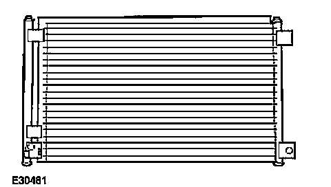
- It is an aluminum fin and tube design heat exchanger located in front of the vehicle radiator.
- It cools compressed refrigerant gas by allowing air to pass over fins and tubes to extract heat and by condensing gas to liquid refrigerant as it is cooled.
- The tube assembly mounted on the side of the condenser core contains the desiccant bag.
Desiccant bag
The desiccant bag removes any retained moisture in the A/C system. The A/C system has an R-134a leak trace dye wafer incorporated into the desiccant bag.
Refrigerant Lines
The manifold and tube assembly - thermostatic expansion valve carries high pressure liquid to the thermostatic expansion valve and low pressure gas from the thermostatic expansion valve to the manifold and tube assembly-compressor.
The manifold and tube assembly - A/C compressor carries the high pressure gas from the A/C compressor to the condenser core. It also carries the low pressure gas received from the manifold and tube assembly-thermostatic expansion valve to the compressor, houses the low pressure service port and has a serviceable high pressure relief valve.
- The manifold and tube assembly - A/C compressor used vehicles with fitted 4.2L engine are are not interchangeable With vehicles fitted with 2.5L and 3.0L engine.
Evaporator Core
The A/C evaporator core is the plate/fin type with a unique refrigerant flow path.
- A mixture of refrigerant and oil exits the thermostatic expansion valve (TXV) and enters the evaporator tank area through the 12.7 mm (0.5 in) tube.
- The tank area is divided into three sections: front inlet, front outlet and rear tank.
- The refrigerant enters the evaporator core tank area at the front inlet, flows down through the core and up the back side in a 'U-flow' pattern.
- The refrigerant moves into the rear tank area and across to the other half of the core. The refrigerant moves down through the core and back up the front side of the core to the front outlet tank area.
- The refrigerant at this point is in a gaseous state. It exits the evaporator through the 16 mm (0.64 in) tube then passes through the TXV.

The thermostatic expansion valve has the following characteristics:
- It is mounted on the evaporator core supply and return lines.
- It is a block-type valve.
- It contains an internal sensing bulb to increase the effectiveness of temperature sensing.
- It is not serviceable. A new thermostatic expansion valve must be installed as a unit.
Pressure cutoff switch
The pressure cutoff switch monitors the A/C compressor discharge pressure and communicates with the ECM. The ECM will interrupt A/C compressor operation in the event that the pressure cutoff switch indicates high system discharge pressures. It is also used to sense no or low charge conditions. If the pressure is below a predetermined value for a given ambient temperature, the ECM will not allow the clutch to engage.
- The pressure cutoff switch is mounted on a Schrader-type valve fitting on the compressor to condenser discharge line.
- A valve depressor, located inside the threaded end of the pressure cutoff switch, presses on the Schrader valve stem and allows the pressure cutoff switch to monitor the compressor discharge pressure.
- When the compressor discharge pressure rises to approximately 2,896 kPa (420 psi), the ECM will interrupt the compressor clutch coil circuit and disengage the compressor.
- When the pressure drops to approximately 1,724 kPa (250 psi) the ECM will enable the A/C compressor circuit.
- Controls the signal to the ECM to control the fan speed.
Service Gauge Port Valves
WARNING: Wear eye protection when opening/servicing the service gauge port valves.
The high-pressure service gauge port valve is located on the tube assembly - condenser to thermostatic expansion valve.
The low pressure service gauge port valve is located on the manifold and tube assembly - A/C compressor.
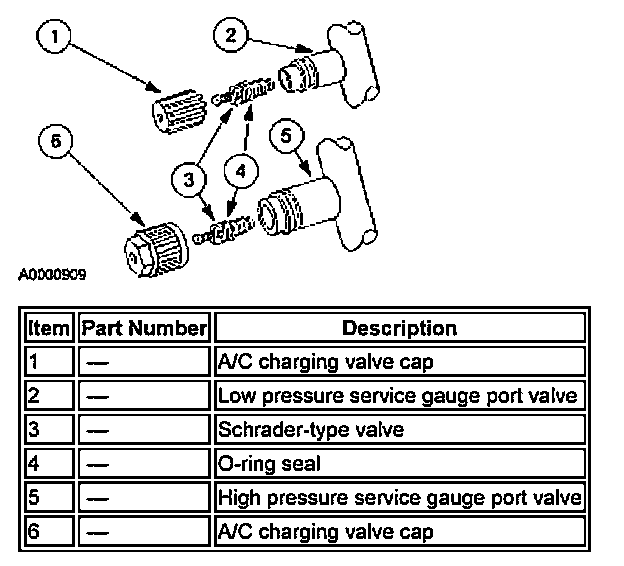
The fitting is an integral part of the refrigerant line or component.
- Special couplings are necessary for both the high side and low side service gauge ports.
- A new Schrader-type valve can be installed if the seal leaks
- Always install the A/C charging valve cap on the service gauge port valves after repairing the refrigerant system.