Part 2
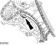
68. Install the primary timing chain tensioner guide.
^ Tighten to 12 Nm.

69. CAUTION: During timing chain tensioner compression, do not release the ratchet stem until the timing chain tensioner piston is fully bottomed in its bore or damage to the ratchet stem will result.
Using a suitable tool, hold the right-hand timing chain tensioner ratchet lock mechanism away from the ratchet stem.
70. NOTE: The timing chain tensioner piston should retract with minimal force. If binding occurs, reposition the timing chain tensioner to eliminate side loading.
Slowly compress the right-hand timing chain tensioner.

71. NOTE: The retaining tool must remain in the timing chain tensioner until the timing chain tensioner is installed to the engine with the piston bottomed in the bore.
Using a suitable tool, retain the right-hand timing chain tensioner piston.

72. Install the primary timing chain tensioner assembly.
^ Tighten to 12 Nm.
73. Release the tension in the right-hand timing chain tensioner.
^ Remove the retaining tool.

74. CAUTION: While applying the opposing force to sprocket and chain, tighten the sprocket bolt.
Using the special tool apply force to the tool in an anti-clockwise direction to tension the primary timing chain on its drive side.
^ Tighten to 120 Nm.

75. CAUTION: While applying the opposing force to sprocket and chain, tighten the sprocket bolt.
Using the special tool apply force to the tool in an anti-clockwise direction.
^ Tighten to 120 Nm.

76. Remove the special tool from the right-hand cylinder head.

77. Remove the special tool from the left-hand cylinder head.

78. Install the left-hand variable camshaft timing oil control unit housing.
^ Install new O-ring seals.
^ Tighten to 22 Nm.

79. Install the right-hand variable camshaft timing oil control unit housing.
^ Install new O-ring seals.
^ Tighten to 22 Nm.

80. Remove the special tool.

81. Install the crankshaft position sensor.
^ Tighten to 10 Nm.

82. Install new seals to the timing cover.
1. Install the new seal to the inner groove on the face of the timing cover.
2. Install the new seal to the outer groove on the face of the timing cover.

83. Apply sealant to the eight joints on the engine face.
^ Sealant beads to be 3mm diameter and 12mm long. Cut the nozzle of the sealant tube to produce a 3 mm bead. (Install and tighten the securing bolts within twenty minutes of sealant application).

84. Install the timing cover.
^ Tighten in the sequence shown.
^ Tighten to 13 Nm.

85. CAUTION: Make sure the crankshaft front seal mating faces are clean and dry.
CAUTION: Do not remove the crankshaft front seal protector.
Using the special tool, install a new crankshaft front seal.

86. Remove the crankshaft seal protector.
87. Install a new O-ring seal to the crankshaft pulley.
^ Lubricate the new O-ring

88. CAUTION: The screw thread in the crankshaft must be cleaned out before a new crankshaft pulley bolt is installed.
CAUTION: A new crankshaft pulley bolt must be used.
Install, but do not tighten, a new crankshaft pulley retaining bolt.
^ Install the crankshaft pulley and locking ring to the crankshaft.

89. CAUTION: Under no circumstances should the crankshaft setting peg 303-645 be used in the following operations to lock the crankshaft.
Using special tools, retain the crankshaft pulley.
^ Tighten the crankshaft pulley retaining bolt to 375 Nm.
90. Remove the special tools.
91. Carry out a valve clearance check.

92. NOTE: Apply an 8mm diameter bead of silicone gasket sealant on the two places where the cylinder head and front cover join.
Install the left-hand valve cover.
^ Install new valve cover gaskets.
^ Tighten in the sequence shown.
^ Tighten to 10 Nm.

93. NOTE: Apply an 8mm diameter bead of silicone gasket sealant on the two places where the cylinder head and front cover join.
Install the right-hand valve cover.
^ Install new valve cover gaskets.
^ Tighten in the sequence shown.
^ Tighten to 10 Nm.
94. Install the spark plugs.
^ Tighten to 27 Nm.

95. Install the left-hand camshaft position (CMP) sensor.
^ Install a new O-ring seal.
^ Tighten to 7 Nm.

96. Install the right-hand camshaft position (CMP) sensor.
^ Install a new O-ring seal.
^ Tighten to 7 Nm.

97. NOTE: Left-hand shown, right-hand similar.
Install the ignition coils.
^ Tighten to 5 Nm.

98. Install the thermostat housing.
^ Install new O-ring seals.
^ Tighten to 10 Nm.

99. Install the water pump.
^ Install new O-ring seals and gaskets.
^ Tighten to 12 Nm.

100. Install the water pump pulley.
^ Using special tool, retain the water pump pulley.
^ Tighten to 10 Nm + 45 degrees.

101. Install the engine block insulation grommet.

102. Install the intake manifold heater coolant hose.
1. Install the knock sensors.
^ Tighten to 20 Nm.
2. Install the intake manifold heater coolant hose.

103. Install the noise and vibration insulating pad.
104. Install the engine wiring harness.

105. Attach the engine wiring harness retaining clips.

106. Attach the right-hand oxygen sensor.
^ Tighten to 10 Nm.

107. Install the oil filter housing.
^ Install a new O-ring seal.
^ Tighten to 21 Nm.

108. Connect the oil pressure switch and oil temperature sensor electrical connectors.

109. Install the oil cooler.
^ Install a new O-ring seal.
^ Tighten to 55 Nm.

110. NOTE: Apply a suitable amount of clean engine oil to lubricate the oil filter O-ring seal.
Install a new oil filter.
^ Tighten to 18 Nm.
111.

112. Install the intake manifold.
^ Tighten to 22 Nm.

113. Attach the engine wiring harness.
^ Tighten to 10 Nm.

114. NOTE: Left-hand shown, right-hand similar.
Install the lower intake manifold.
^ Tighten to 22 Nm.

115. Attach the engine wiring harness.

116. Connect the camshaft position sensor electrical connector.

117. Connect the fuel temperature sensor electrical connector.

118. Connect the ignition on-plug coil electrical connectors.

119. Attach the engine wiring harness.

120. Connect the fuel injector electrical connectors.

121. Attach the engine wiring harness.

122. Connect the exhaust gas recirculation valve coolant hose.

123. Connect the exhaust gas recirculation valve electrical connector.

124. Connect the fuel pressure regulator electrical connector.

125. Connect the positive crankcase ventilation pipe.

126. Attach the engine wiring harness.

127. Attach the engine wiring harness.

128. Attach the engine harness.
1. Connect the earth wire.
2. Connect the variable valve timing (VVT) solenoid electrical connector.
^ Attach the engine harness.

129. Connect the camshaft position sensor electrical connector.

130. Attach the engine wiring harness.

131. Attach the engine wiring harness.

132. Connect the ignition on-plug coil electrical connectors.

133. NOTE: Left-hand shown, right hand similar.
Connect the fuel injector electrical connectors.

134. Attach the engine wiring harness.

135. Install the engine cover retaining bracket.