Part 2
Speed Control
SYSTEM RESTRICTIONS
The adaptive speed control system is only intended to provide enhanced speed control as described above in certain restricted conditions. The following points should be noted:
- Automatic braking is limited to approximately 30% of full pressure (0.3G deceleration) and is intended to provide a smooth, gradual deceleration in follow mode conditions. Harsh braking by the target vehicle or following the target vehicle down to very low speeds or to a halt will require the driver to intervene and override the brakes. A 'driver intervene' message will be displayed in the message center accompanied with an audible chime.
- While the radar sensor detects moving and stationary targets for assessment of the environment ahead, the system does not react to or provide any control in situations other than follow mode conditions. Stationary or slow moving vehicles (below 10 km/h), pedestrians, objects on the road and oncoming vehicles in the same lane are not recognized.
WARNING: It must be emphasized that the adaptive speed control system is not a collision warning or avoidance system and that, other than the limited conditions of follow mode, driver intervention will be necessary to control the vehicle speed.
The following illustration shows circumstances where the adaptive cruise control system may brake late or unexpectedly. The driver is required to intervene in these situations.


In follow mode, some situations may cause target ambiguities for the detection system. These situations include:
- The nearby presence of a third vehicle when driving on a line slightly offset to the target vehicle.
- Vehicles edging into the lane ahead which are not detected by the system until they have moved into the radar beam.
On the approach to, or exit from a bend, a target vehicle may be lost or a new target acquired as vehicles ahead change their angular position with respect to the radar sensor. On a straight road, if the sensing vehicle is in follow mode below its selected set speed, losing the target vehicle will cause the sensing vehicle to accelerate to this set speed. This acceleration is undesirable either on, or entering a bend when the target is suddenly lost, and in this situation the system inhibits the resumption of the set speed.
The speed control system compares vehicle speed data from the ABS (anti-lock brake system) system with the relative speed of an external object as detected by the radar sensor to ascertain whether the object is stationary or not.
NOTE:
If tires are fitted which are different in diameter from those specified for the vehicle, the vehicle speed calculated by the ABS (anti-lock brake system) will not be the true road speed. This situation may cause stationary objects to be falsely identified as moving vehicles and result in automatic deceleration on a clear road.
BRAKE SYSTEM FUNCTIONS
Electronic Brake Prefill
Electronic brake prefill senses any rapid throttle lift off, activating a small brake hydraulic pressure build-up of approximately 3 to 5 bar (43.5 to 72.5 lbf/in2) in anticipation of the brakes being applied.
This application produces a quicker brake pedal response and consequently slightly shorter stopping distances. The system supports vehicles with adaptive speed control.
When the ABS (anti-lock brake system) module detects rapid throttle lift off (signal received from the ECM (engine control module) over the high speed CAN (controller area network) bus), it controls the ABS (anti-lock brake system)
HCU (hydraulic control unit) to apply a low brake pressure to assist in a quicker brake application.
Emergency Brake Assist
EBA (emergency brake assist) assists the driver in emergency braking situations by automatically increasing the applied braking effort. The ABS (anti-lock brake system) module activates EBA (emergency brake assist) when:
- The brake pedal is rapidly pressed
- The brake pedal is pressed hard enough to bring the front brakes into ABS (anti-lock brake system) operation.
When the brake pedal is rapidly pressed, the ABS (anti-lock brake system) module increases the hydraulic pressure to all of the brakes until the threshold for ABS (anti-lock brake system) operation is reached. This action applies the maximum braking effort for the available traction. The ABS (anti-lock brake system) module monitors for the sudden application of the brakes, using inputs from the brake pedal switch and from the pressure sensor within the HCU (hydraulic control unit) With the brake pedal pressed, if the rate of increase of hydraulic pressure exceeds the predetermined limit, the ABS (anti-lock brake system) module activates emergency braking.
When the brake pedal is pressed hard enough to bring the front brakes into ABS (anti-lock brake system) operation, the ABS (anti-lock brake system) module increases the hydraulic pressure to the rear brakes up to the ABS (anti-lock brake system) threshold.
EBA (emergency brake assist) operation continues until the driver releases the brake pedal, sufficiently for the hydraulic pressure in the HCU (hydraulic control unit) to drop below a threshold value stored in the ABS (anti-lock brake system) module.
Advanced Emergency Brake Assist
Advanced EBA (emergency brake assist) uses adaptive speed control technology to provide pre-emptive control when sudden braking is required. The system is an enhancement of electronic brake prefill and emergency brake assist. The system can sense the possibility of a collision before the driver reacts through the brake pedal and can prepare the braking process even before the driver reacts and moves to the brake pedal, thus when the driver takes action, the braking system can respond to emergency braking more promptly, potentially avoiding a collision entirely, or mitigating the effects if a collision is inevitable. The system activates if the risk of collision increases after the forward alert warning is issued.
After a forward alert warning is displayed, the brakes are automatically applied gently in preparation for rapid braking and the EBA (emergency brake assist) activation threshold is lowered. If the brake pedal is then pressed quickly then braking is fully implemented by the emergency brake assist system, even if the pressure on the brake pedal is light.
The system operates using signals from the adaptive speed control module, based on proximity to and closing speed to the vehicle in front by monitoring forward traffic and obstructions with the radar sensor used by adaptive speed control. Through the positive brake-line pressure available from the HCU (hydraulic control unit), it will apply a pre-charge of brake pressure even before the driver reacts. Thresholds for the entry to EBA (emergency brake assist) are reduced so that the system functions earlier than it would without the data from the radar sensor.
Advanced EBA (emergency brake assist) is available at speeds above 5 mph (7 km/h) and will function even when forward alert and adaptive speed control are switched off.
Principle of Operation - Advanced Emergency Brake Assist
The radar sensor detects vehicles ahead that are moving in the same direction as the host vehicle. In the event of a collision risk, and 'Forward Alert' is on, the driver is initially alerted by a visual and audible warning signal. If the risk of collision increases after the warning, advanced EBA (emergency brake assist) maybe activated. The advanced EBA (emergency brake assist) prepares the brake system for rapid braking with the brakes being applied gently. If the brake pedal is depressed quickly then braking is implemented with full brake function, even if the force on the pedal is light.
The forward alert and Advanced EBA (emergency brake assist) system response to an imminent rear-end collision with another moving vehicle reacts in the following order:
- Forward alert
- Collision warning - audible and visual (driver can turn this function off)
- Advanced Emergency Brake Assist
- 1st stage precharge - If a collision is judged to be credible and the driver takes no action then Advanced EBA (emergency brake assist) will prepare the brake system by requesting a fixed precharge brake pressure (approximately 3 bar). Reduction of EBA (emergency brake assist) activation threshold provides a faster entry to the full EBA (emergency brake assist) function.
- 2nd stage precharge - If a collision is judged to be imminent and the driver shows an intent to respond to the threat, for example; quick release of the throttle, Advanced EBA (emergency brake assist) will request that the brake system applies a fixed brake pressure (approximately10 bar).
NOTE:
If the throttle is already released, precharge 1 and 2 occurs simultaneously (the system moves directly to precharge level 2).


EBA (emergency brake assist) is designed to detect an emergency braking situation giving an automatic increase in vehicle deceleration, up to ABS (anti-lock brake system) levels. This quick, increase, in braking deceleration assists the 'average' driver to achieve a reduced stopping distance.
Advanced EBA (emergency brake assist) enhances the performance of EBA (emergency brake assist). When a critical approach to forward vehicles is detected Advanced EBA (emergency brake assist) requests a pre-charge pressure to the brake system and increases the sensitivity for activation of EBA (emergency brake assist).
The graph below shows a comparison of 'normal' braking, EBA (emergency brake assist) and Advanced EBA (emergency brake assist) brake pressure profiles.


NOTE:
The system:
- Only operates at speeds above 5 mph (7 km/h)
- Responds only to vehicles moving in the same direction as the host vehicle
- Is designed to help reduce the crash speed and damage in certain rear-end collisions only
- Is not a collision avoidance system and is not a substitute for safe and attentive driving
- Effectiveness depends on many factors, such as speed, driver input, and road conditions
- DOES NOT WARN FOR STATIONARY OR SLOW MOVING VEHICLES
- The driver should always keep a safe following distance.
NOTE:
The stop lamps will always be activated on application of the service brakes including all electronic braking interventions (pre-charge, brake assist etc.).
Advanced Emergency Brake Assist - Malfunction Warnings
If the Advanced EBA (emergency brake assist) system is in a fault condition for five consecutive ignition cycles the 'Forward Alert Not Available' fault message will be permanently displayed.
SPEED CONTROL SWITCHES


The speed control switches are located on the RH (right-hand) side of the steering wheel. The switches are connected via fly leads to the clock spring. The speed control switches are resistive ladder type switches which vary the resistance of a 5 volt signal sent to them. The signal is returned along a LIN (local interconnect network) bus, via the clockspring to the CJB (central junction box). The CJB (central junction box) routes the control signals to the ECM (engine control module) on the high speed CAN (controller area network) bus.
Speed control is engaged by pressing the set speed switch (+). Once engaged the speed can be varied by the set speed adjustment switches (+ or -). Each press of the speed adjustment switch will increase or decrease the set speed in steps of 1 mph (2 kph).
Gap Setting Display Options


The gap settings are changed using the time gap increase and decrease switches which are located on the RH (right-hand) side of the steering wheel. The switches are connected via fly leads to the clock spring. The gap switches are resistive ladder type switches which vary the resistance of a 5 volt signal sent to them. The signal is returned along a LIN (local interconnect network) bus, via the clockspring to the CJB (central junction box). The CJB (central junction box) routes the selected gap setting signals to the ECM (engine control module) on the high speed CAN (controller area network) bus.
The time gap will return to the default gap (the third setting) each time the ignition is cycled.
ADAPTIVE SPEED CONTROL MODULE
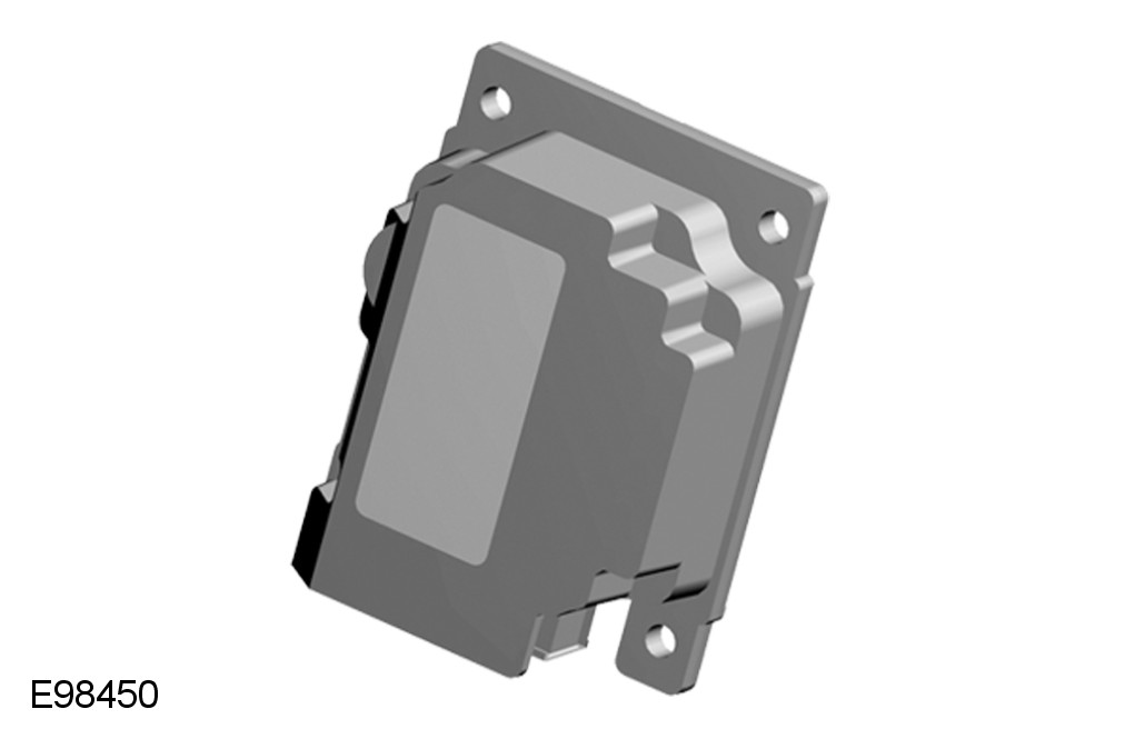
The adaptive speed control module is located on the drivers side at the bottom of the A pillar. The control module is connected to the other vehicle systems via the high speed CAN (controller area network) bus. Signals from the adaptive speed control forward looking radar sensor are received on a dedicated CAN (controller area network) bus between the two modules.
ADAPTIVE SPEED CONTROL RADAR SENSOR
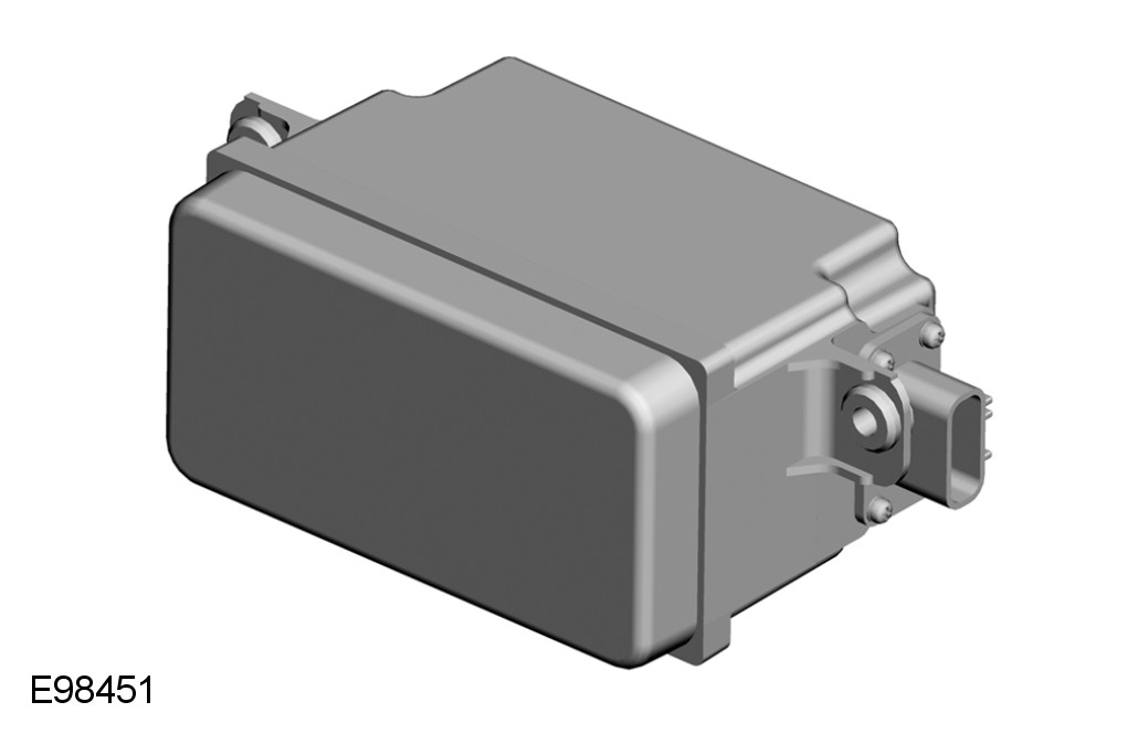
The adaptive speed control radar sensor is located in the front bumper, on the RH (right-hand) side above the radiator grill behind the bumper cover. The sensor is connected to the adaptive speed control module via a private CAN (controller area network) bus. If the unit is replaced in service the unit must be re-aligned vertically. Horizontal alignment is achieved by putting the sensor in service mode using an approved Jaguar diagnostic system.
The vehicle is then driven for a short period while the sensor calibrates itself. Calibration is complete when the 'follow' icon in the instrument cluster stops flashing.
Service Alignment Process
The service alignment process measures the path of stationary targets such as streetlights, railings, road signs, parked vehicles etc., and uses this data to correct for radar misalignment. Alignment will complete more quickly if more suitable targets are seen. The following recommendations should be followed:
- Vehicle speed must be above 30mph (48kph)
- Attempt to keep the vehicle speed about the same. The process will take longer to complete if the speed varies too much.
- Choose a road with plenty of stationary objects, like lamp posts, railings, street signs or parked vehicles. Use an inside or outside lane
- Following vehicles too closely will obscure the stationary targets from the radar, a time gap of at least 2 seconds is recommended
- A straighter road will produce a quicker and better result, although the process will still operate on a curved road
- The time the module takes to align will vary, depending on the route, speed, number of targets, and the individual module
SPEED CONTROL WARNING INDICATORS


ADAPTIVE SPEED CONTROL - MALFUNCTION WARNINGS
If a malfunction occurs during operation of the system in adaptive speed control or follow modes, the adaptive speed control system will switch off and cannot be used until the fault is cleared. The message 'Driver Intervene' appears briefly and is then replaced by the message 'Cruise Not Available'. If a malfunction of the adaptive speed control, or any related system occurs at any other time, the message 'Cruise Not Available' will be displayed. It will not be possible to activate the adaptive speed control system in any mode.
Accumulations of dirt, snow or ice on the radar sensor or cover may inhibit adaptive speed control operation. Fitting of a vehicle front protector or metallized badges may also affect adaptive speed control operation. The adaptive speed control system relies on its radar to detect objects and constantly scans ahead. If the radar detects no vehicles ahead in adaptive speed control or follow mode, then the adaptive speed control will be deactivated, the audible alarm sounds and the message 'Driver Intervene' displays briefly. The message 'ACC Sensor Blocked' follows the previous message. The same messages may also be displayed while driving on open roads with few objects for the radar to detect. Clearing the obstruction allows the system to return to normal operation. If the obstruction is present when adaptive speed control is inactive (e.g. on initial starting or with the system switched off), the message 'ACC Sensor Blocked' will be displayed.