Without Tilt
REMOVAL
NOTE: Steering column removal from the vehicle is not necessary for Ignition key/lock cylinder service.
1. Remove the steering wheel.
2. Remove the lockplate cover.
WARNING: THE LOCKPLATE RETAINS A VERY STRONG, SPRING FORCE. DO NOT ATTEMPT TO REMOVE THE STEERING SHAFT RETAINING SNAP RING WITHOUT USING LOCKPLATE COMPRESSOR C-41 56 (J23653-B).
Retaining Snap Ring Removal:
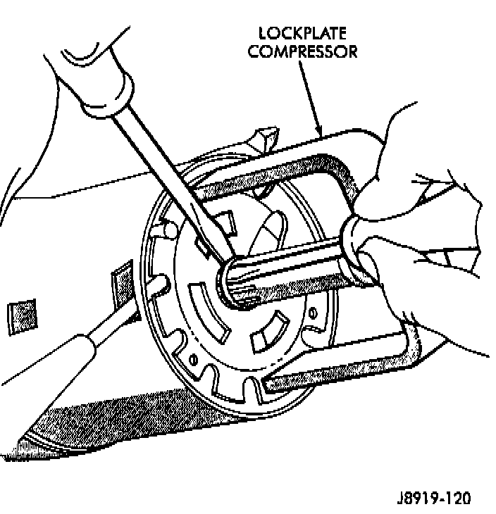
3. Compress the lockplate with Compressor C-4156 (J-23653-B) and release the steering shaft retaining snap ring.
4. Remove the lockplate compressor tool and the retaining snap ring. Discard the snap ring.
CAUTION: When the steering shaft retaining snap ring is removed, the steering shaft is no longer retained within the column.
Steering Column Disassembly:
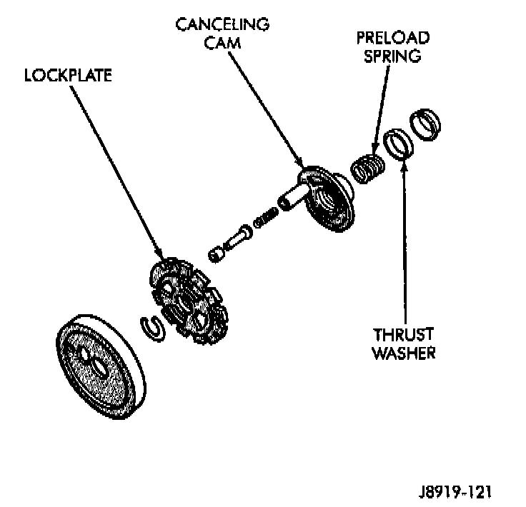
5. Remove the lockplate, canceling cam, upper bearing preload spring, and the thrust washer from the steering column/shaft.
6. Remove the hazard warning switch knob. Press the knob inward and remove it from the column by turning it counterclockwise.
7. Remove the turn signal/wiper/cruise control stalk by pulling it out straight from the column. Wiper must be in the off position.
8. Disconnect the turn signal wire harness connector from the bracket.
Taped Turn Signal Switch Wire Harness Connector:
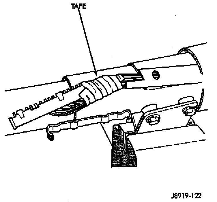
CAUTION: Wrap tape around the turn signal switch wire harness connector to prevent it from becoming entangled during removal.
Turn Signal Switch Retaining Screw:
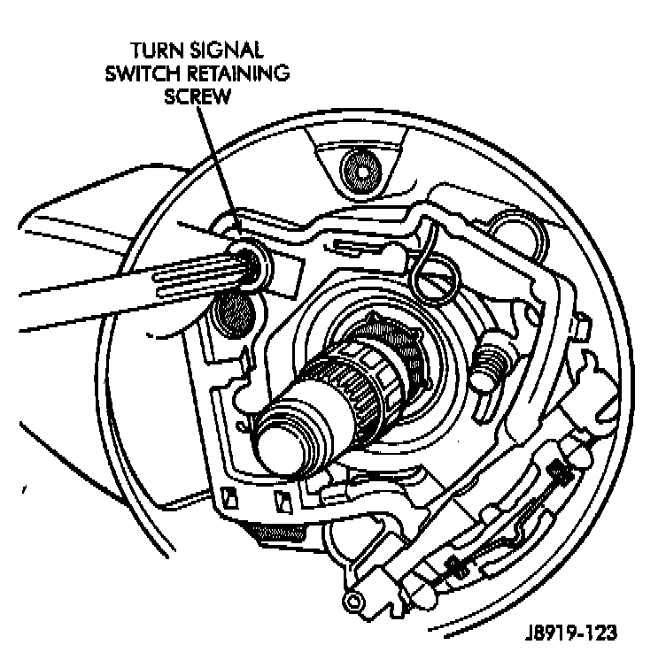
9. Remove the turn signal switch retaining screws, dimmer switch actuator arm, to remove the switch. Guide the switch straight up and out of the steering column.
10. Remove the wiper switch wire harness and all the other wire harnesses located within the steering column.
11. Insert the ignition switch key into the key/ lock cylinder and turn to the ON position.
CAUTION: Do not attempt to remove the key warning buzzer switch and contacts separately. If separated, the contacts can detach and drop into the steering column.
Key Warning Buzzer/Contacts Removal:
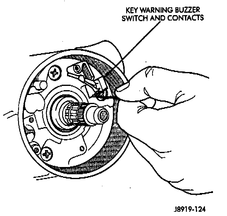
12. Remove the key warning buzzer switch and contacts as a unit. Use needle-nose pliers or a paper clip bent at a right angle (90 degrees).
Key/Lock Cylinder Removal:
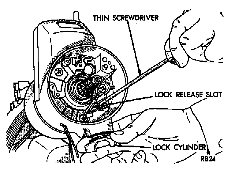
13. Turn ignition key/lock cylinder to the ON position. Insert a thin screwdriver into the slot adjacent to the switch attaching screw boss (right-hand slot). Depress the spring latch located at the bottom of the slot to release the key/lock cylinder. Remove the key/lock cylinder.
INSTALLATION
Installation is the reverse of removal.