PDC Relay Cassete
REMOVALThe Power Distribution Center (PDC) cover, the PDC housing lower cover, the PDC relay wedges, the PDC relay cassettes and the PDC B(+) terminal stud module are available for service replacement. The PDC cover can be simply unlatched and removed from the PDC housing without the PDC being removed or disassembled. Service of the remaining PDC components requires that the PDC be removed from its mounting and disassembled. Refer to Wiring Repair in Wiring Diagrams for the location of the wiring repair procedures.
1. Remove the relay wedge from the PDC relay cassette to be removed.
NOTE: It may be necessary to remove relay cassettes that are not being serviced from the PDC housing in order to obtain sufficient clearance to access the faulty relay cassette. The same service procedure is repeated as necessary to remove each of the interfering relay wedges and relay cassettes from the PDC housing.
Pdc Relay Cassette Latches-typical:
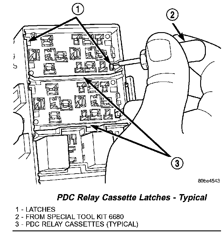
2. From the top of the PDC housing, use a small screwdriver or a terminal pick tool (Special Tool Kit 6680) to release the two latches that secure the relay cassette in the PDC.
3. Gently and evenly press the relay cassette down through the PDC housing.
Pdc Relay-typical:
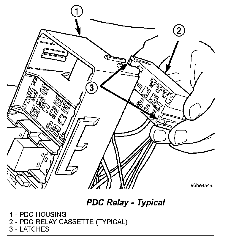
4. From the bottom of the PDC housing, remove the relay cassette from the PDC.
CAUTION: Do not remove the wiring and terminals from the terminal cavities of the faulty PDC relay cassette at this time. Refer to the Assembly procedure that follows for the proper procedures for transferring the wiring and terminals to the replacement PDC relay cassette.
INSTALLATION
1. Move the faulty PDC relay cassette with its wiring away from the bottom of the PDC housing far enough to allow the replacement relay cassette to be installed into the PDC.
2. Using the faulty relay cassette as a guide, be certain that the replacement relay cassette is correctly oriented before installing it into the PDC housing.
3. From the bottom of the PDC housing, align and insert the replacement relay cassette into the PDC. Press the relay cassette up into the PDC until both of the latches are fully engaged.
CAUTION: Proper care must be taken to be certain that the wiring and terminals from the faulty PDC relay cassette are installed in the correct terminal cavities of the replacement relay cassette. To prevent mistakes it is recommended that the wiring and terminals be removed from the faulty relay cassette one cavity at a time, repaired or spliced as necessary, then installed securely into the correct cavity of the replacement relay cassette. If you are not absolutely certain into which cavity a terminal should be installed, refer to Power Distribution in the index of this service manual for the location of complete circuit diagrams covering the PDC.
PDC Relay Cassette Terminal Remove/install:
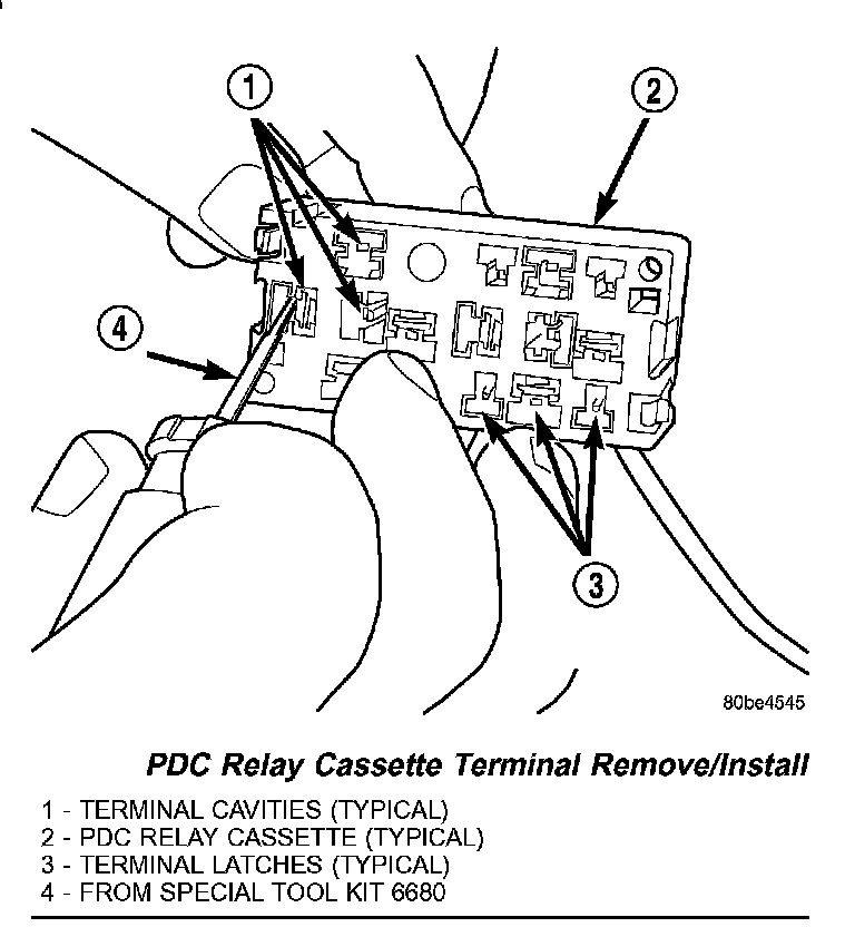
4. While pulling gently on the wire from the bottom of the faulty PDC relay cassette, use a terminal pick tool (Special Tool Kit 6680) from the top of the relay cassette to release the latch that secures the terminal in the relay cassette terminal cavity.
5. From the bottom of the faulty PDC relay cassette, remove the wire and terminal from the relay cassette terminal cavity.
6. Make all necessary repairs and splices to the wire for the removed terminal. Refer to Wiring Repair in Wiring Diagrams for the location of the wiring repair procedures.
7. From the bottom of the PDC housing, align and insert the removed wire and terminal into the correct terminal cavity of the replacement relay cassette. Push the wire and terminal up into the relay cassette terminal cavity until it is fully engaged by the latch.
8. Repeat Step 4, Step 5, Step 6 and Step 7 one wire and terminal at a time until each of the wires and terminals have been transferred from the faulty PDC relay cassette into the replacement relay cassette.
9. Install the PDC relay wedge into the replacement PDC relay cassette.