P127F
P127F-FUEL PUMP CONTROL CIRCUIT 2 OVERCURRENT

For a complete wiring diagram, refer to the Wiring Information Electrical Diagrams.
- When Monitored:
With the ignition on. Battery voltage greater than 10.4 volts. Totally Integrated Power Module (TIPM) requesting fuel pump operation.
- Set Condition:
An overcurrent condition is detected in the Fuel Pump control output circuit. One Trip Fault. Three good trips to turn off the MIL.

Always perform the Pre-Diagnostic Troubleshooting procedure before proceeding. Pre-Diagnostic Troubleshooting Procedure.
1. DTC IS ACTIVE
NOTE: If P0627, P0628 or P0629 has set along with this DTC, diagnose those DTCs first before continuing.
1. Ignition on, engine not running.
2. With the scan tool, select View DTCs.
Is the status Active for this DTC?
Yes
- Go To 2
No
- Perform the CHECKING FOR AN INTERMITTENT DTC diagnostic procedure. Checking for an Intermittent DTC.
2. VISUAL AND PHYSICAL CONNECTOR AND TERMINAL INSPECTION
1. Turn the ignition off.
2. Disconnect the TIPM C7 harness connector.
3. Disconnect the Fuel Pump harness connector.
4. Inspect the terminal and connector condition. Check for signs of corrosion build up or damage the would compromise the terminal to controller pin connector.
NOTE: Make sure that all in-line connectors are inspected for corrosion and/or damage.
5. Visually inspect the wiring harness. Look for any chafed, pierced, pinched or partially broken wires hidden in the wire insulation.
6.
Were any of the above conditions found?
Yes
- Repair or replace as necessary.
- Perform the BODY VERIFICATION TEST. Body Verification Test.
No
- Go To 3
3. (N1) FUEL PUMP CONTROL OUTPUT CIRCUIT HIGH RESISTANCE

1. With a jumper wire, connect one end to the (N1) Fuel Pump Control Output circuit in the Fuel Pump harness connector and the other to a clean chassis ground.
2. Using a 12-volt test light to battery voltage, probe the (N1) Fuel Pump Control Output circuit in the TIPM C7 harness connector.
NOTE: The test light should be illuminated and bright. Compared the brightness to that of a direct connection to the battery.
Does the test light illuminate brightly.
Yes
- Go To 4
No
- Repair the high resistance in the (N1) Fuel Pump Control Output circuit.
- Perform the BODY VERIFICATION TEST. Body Verification Test.
4. (Z906) FUEL PUMP GROUND CIRCUIT
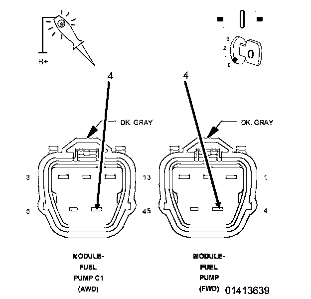
1. Using a 12-volt test light to battery voltage, probe the (Z906) Fuel Pump Ground circuit in the Fuel Pump harness connector.
NOTE: The test light should be illuminated and bright. Compared the brightness to that of a direct connection to the battery.
Does the test light illuminate brightly?
Yes
- Go To 5
No
- Repair the excessive resistance in the (Z906) Fuel Pump Ground circuit.
- Perform the BODY VERIFICATION TEST. Body Verification Test.
5. (N1) FUEL PUMP CONTROL OUTPUT CIRCUIT

1. Reconnect the TIPM C7 harness connector.
2. Ignition on, engine not running.
3. With a scan tool in the TIPM Actuators, actuate the Fuel Pump.
4. Using the 12-volt test light connected to ground, probe the (N1) Fuel Pump Control Output circuit in the Fuel Pump harness connector.
Does the test light illuminate brightly?
Yes
- Replace the Fuel Pump.
- Perform the BODY VERIFICATION TEST. Body Verification Test.
No
- Replace the Totally Integrated Power Module (TIPM).
- Perform the BODY VERIFICATION TEST. Body Verification Test.