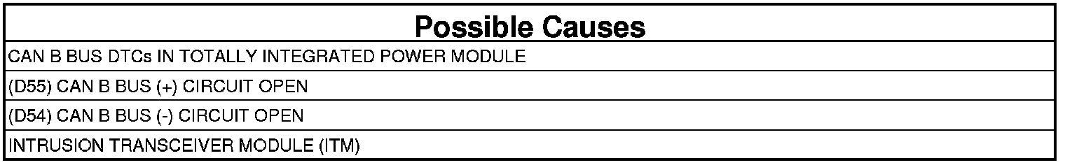
Intrusion Transceiver Module (ITM)
U0019-CAN B BUS

For a complete wiring diagram, refer to the Wiring Information Electrical Diagrams.
- When Monitored:
Continuously
- Set Condition:
Whenever the CAN B Bus (+) or CAN B Bus (-) circuit is open, shorted to voltage or shorted to ground.
1. CHECK FOR ACTIVE DIAGNOSTIC TROUBLE CODE (DTC)S
1. With the scan tool, read the active DTCs.
2. Cycle the ignition switch from off to on at least 5 times, leaving the ignition on for a minimum of 90 seconds per cycle.
3. With the scan tool, read the active DTCs.
Does the scan tool display this DTC as active?
Yes
- Go To 2
No
- If the DTC is stored, check for an intermittent condition. Visually inspect the related wiring harness connectors. Look for broken, bent, pushed out, or corroded terminals.
2. CHECK TOTALLY INTEGRATED POWER MODULE DTCs
1. With the scan tool, read Totally Integrated Power Module (TIPM) active DTCs.
Does the scan tool display any CAN B BUS DTCs as active?
Yes
- Go to and perform the appropriate diagnostic procedure.
No
- Go To 3
3. (D55) CAN B BUS (+) CIRCUIT OPEN
1. Turn the ignition off.
2. Disconnect the negative battery cable.
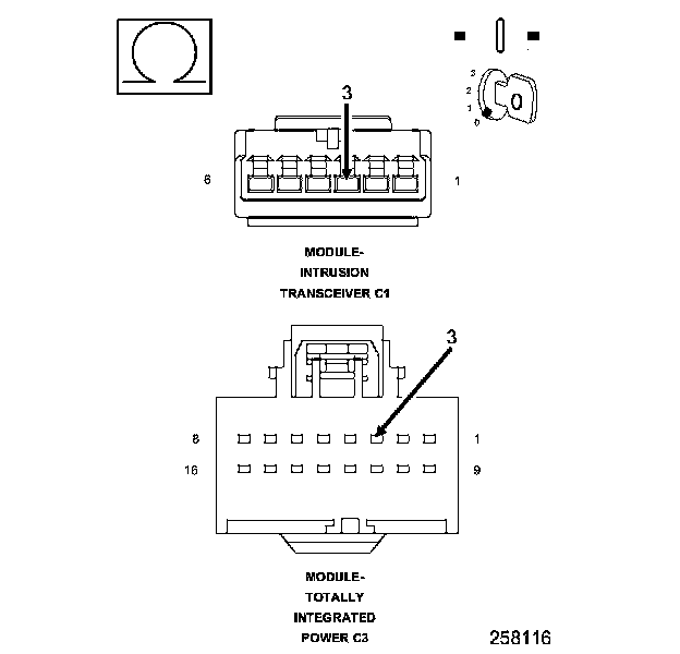
3. Disconnect the ITM harness connector.
4. Disconnect the TIPM C3 connector.
5. Measure the resistance of the (D55) CAN B Bus (+) circuit between the TIPM C3 connector and the ITM harness connector.
Is the resistance below 2.0 ohms?
Yes
- Go To 4
No
- Repair the (D55) CAN B Bus (+) circuit for an open.
- Perform the BODY VERIFICATION TEST. Body Verification Test
4. (D54) CAN B BUS (-) CIRCUIT OPEN

1. Measure the resistance of the (D54) CAN B Bus (-) circuit between the TIPM C3 connector and the ITM harness connector.
Is the resistance below 2.0 ohms?
Yes
- Replace the Intrusion Transceiver Module.
- Perform the BODY VERIFICATION TEST. Body Verification Test
No
- Repair the (D54) CAN B Bus (-) circuit for an open.
- Perform the BODY VERIFICATION TEST. Body Verification Test