P2111
P2111-ELECTRONIC THROTTLE CONTROL - UNABLE TO CLOSE

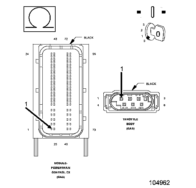
For a complete wiring diagram Refer to the Wiring Information.
- When Monitored:
Ignition on and battery voltage greater than 10 volts.
- Set Condition:
Just after key on, the throttle is opened and closed to test the system. If the PCM detects that the TP Sensor does not return to Limp Home Position, this DTC will set. One trip fault. The DTC will set within 5 seconds. ETC light is flashing.

Always perform the Pre-Diagnostic Troubleshooting procedure before proceeding. Pre-Diagnostic Troubleshooting Procedure.
1. ACTIVE DTC
NOTE: Diagnose any TP Sensor or 5 Volt Supply DTCs before continuing.
NOTE: Maximum engine speed could be reduced while this fault is active, based on where the throttle plate is stuck.
NOTE: The PCM tests the ETC Motor by opening and closing the throttle plate before starting the engine. If the throttle plate does not return to the closed position this DTC will set.
1. Start the engine and allow it to reach normal operating temperature.
WARNING: When the engine is operating, do not stand in direct line with the fan. Do not put your hands near the pulleys, belts or fan. Do not wear loose clothing. Failure to follow these instructions may result in possible serious or fatal injury.
2. With the scan tool, select View DTCs.
Is the status Active for this DTC?
Yes
- Go to 2
No
- Refer to the *CHECKING FOR AN INTERMITTENT DTC Diagnostic Procedure.Checking for an Intermittent DTC
2. THROTTLE PLATE INSPECTION
1. Turn the ignition off.
2. Remove the air cleaner assembly.
3. Check for any signs of a foreign material (ice or dirt) on the throttle plate or in the throttle bore that can cause the throttle plate to stick or not fully close.
4. Attempt to manually open the throttle plate and allow it to close. Use an appropriate tool that will not damage or mar the throttle body.
Were any problems found?
Yes
- Repair as necessary or replace the Throttle Body Assembly. Disconnect the battery when replacing the Throttle Body Assembly. After installation is complete, use a scan tool and select the ETC Relearn function.
- Perform the PCM Verification TestPCM Verification Test.
No
- Go to 3
3. TP SENSOR NO.1 AND TP SENSOR No. 2 BOTH EQUAL 2.5 VOLTS
1. With a scan tool, perform the Throttle Follower test and monitor both TP Sensor voltages.
Are both TP Sensor readings stuck at 2.5 volts?
Yes
- Check the TP Sensor Signal circuits for excessive resistance, being shorted together, or shorted to the Sensor Ground circuit.
- Perform the PCM Verification TestPCM Verification Test.
No
- Go to 4
4. (K124) ETC MOTOR (+) CIRCUIT SHORTED TO VOLTAGE

1. Turn the ignition off.
2. Disconnect the Throttle Body harness connector.
3. Disconnect the PCM harness connectors.
4. Turn the ignition on.
5. Measure the voltage of the (K124) ETC Motor (+) circuit.
Is there any voltage present?
Yes
- Repair the (K124) ETC Motor (+) circuit for a short to voltage.
- Perform the PCM Verification TestPCM Verification Test.
No
- Go to 5
5. (K126) ETC MOTOR (-) CIRCUIT SHORTED TO VOLTAGE

1. Measure the voltage of the (K126) ETC Motor (-) circuit.
Is there any voltage present?
Yes
- Repair the (K126) ETC Motor (-) circuit for a short to voltage.
- Perform the PCM Verification TestPCM Verification Test.
No
- Go to 6
6. (K124) ETC MOTOR (+) CIRCUIT SHORTED TO THE (K126) ETC MOTOR (-) CIRCUIT

1. Turn the ignition off.
2. Measure the resistance between the (K124) ETC Motor (+) circuit and the (K126) ETC Motor (-) circuit.
Is the resistance below 100 ohms?
Yes
- Repair the short to between the (K124) ETC Motor (+) circuit and the (K126) ETC Motor (-) circuit.
- Perform the PCM Verification TestPCM Verification Test.
No
- Go to 7
7. (K124) ETC MOTOR (+) CIRCUIT SHORTED TO GROUND

1. Measure the resistance between ground and the (K124) ETC Motor (+) circuit.
Is the resistance below 100 ohms?
Yes
- Repair the short to ground in the (K124) ETC Motor (+) circuit.
- Perform the PCM Verification TestPCM Verification Test.
No
- Go to 8
8. (K126) ETC MOTOR (-) CIRCUIT SHORTED TO GROUND

1. Measure the resistance between ground and the (K126) ETC Motor (-) circuit.
Is the resistance below 100 ohms?
Yes
- Repair the short to ground in the (K126) ETC Motor (-) circuit.
- Perform the PCM Verification TestPCM Verification Test.
No
- Go to 9
9. (K126) ETC MOTOR (-) CIRCUIT OPEN OR HIGH RESISTANCE

1. Measure the resistance of the (K126) ETC Motor (-) circuit.
Is the resistance below 5.0 ohms?
Yes
- Go to 10
No
- Repair the (K126) ETC Motor (-) circuit for an open circuit or high resistance.
- Perform the PCM Verification TestPCM Verification Test.
10. (K124) ETC MOTOR (+) CIRCUIT OPEN OR HIGH RESISTANCE
1. Measure the resistance of the (K124) ETC Motor (+) circuit.
Is the resistance below 5.0 ohms?
Yes
- Go to 11
No
- Repair the (K124) ETC Motor (+) circuit for an open circuit or high resistance.
- Perform the PCM Verification TestPCM Verification Test.
11. POWERTRAIN CONTROL MODULE (PCM)
1. Using the wiring diagram/schematic as a guide, inspect the wiring and connectors between the Throttle Body and the Powertrain Control Module (PCM).
2. Look for any chafed, pierced, pinched, or partially broken wires.
3. Look for broken, bent, pushed out or corroded terminals.
4. Search for any Technical Service Bulletins that may apply.
Were any problems found?
Yes
- Repair as necessary.
- Perform the PCM Verification TestPCM Verification Test.
No
- Replace and program the Powertrain Control Module.
- Perform the PCM Verification TestPCM Verification Test.