P2770
P2770-TORQUE CONVERTER CLUTCH CIRCUIT HIGH

For a complete wiring diagram, refer to the Wiring Information.
Theory of Operation
The Transmission Control Module monitors two signals from the TCC Solenoid during normal operation. One is the feedback electric current of the TCC Solenoid and the other is the voltage between ground and the TCM termination for the TCC Solenoid.
- When Monitored:
Ignition on, engine running with the transmission in a valid forward gear.
Vehicle speed greater than 10 Km/h (6 mph).
Accelerator Pedal Position (APP) greater than 12.5%.
Engine rpm greater than 450 rpm with TCC lock-up enabled.
TCC Lock up command is ON (True).
No active DTCs from the following:
Torque Convertor Clutch Circuit Low, Step motor, Line Pressure Solenoid, Secondary Solenoid, Input and Output Speed Sensor, Primary or Secondary Pressure Sensor, or CAN BUS.
- Set Condition:
If the target current is greater than 0.75 of an amp and the monitored current is less than 0.4 of an amp for the period of five seconds. It takes two consecutive problem identification trips for the DTC to mature and illuminate the MIL.

Always perform the CVT Pre-Diagnostic Troubleshooting procedure before proceeding. Testing and Inspection.
1. CHECK TO SEE IF THE DTC IS ACTIVE
1. With the scan tool, read Transmission DTCs.
Is the status Active or is the Starts Since Set counter 2 or less for this DTC?
Yes
- Go To 2
No
- Go To 6
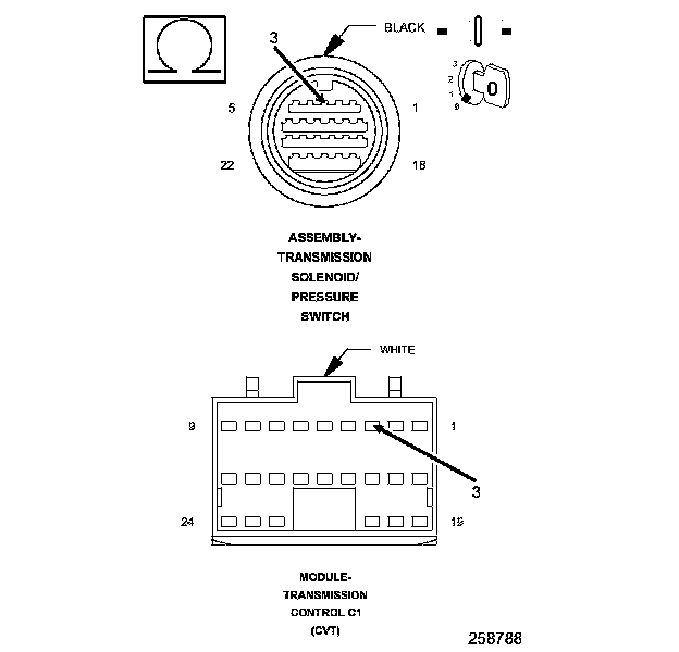
2. CHECK THE (T59) TCC SOLENOID CONTROL CIRCUIT

1. Turn the ignition off to the lock position.
2. Disconnect the Transmission Solenoid/Pressure Switch Assembly harness connector.
3. Ignition on, engine not running.
4. With the scan tool, actuate the (L/U) TCC Solenoid.
5. Using a 12-volt test light connected to ground, check the (T59) TCC Solenoid Control circuit.
NOTE: The test light must illuminate brightly. Compare the brightness to that of a direct connection to the battery.
Does the test light illuminate brightly?
Yes
- Go To 3
No
- Go To 5
3. CHECK THE (T59) TCC SOLENOID CONTROL CIRCUIT FOR A SHORT TO VOLTAGE

1. With the scan tool, stop the TCC Solenoid actuator.
2. Turn the ignition off to the lock position.
3. Disconnect the TCM C1 harness connector.
4. Ignition on, engine not running.
5. Measure the voltage of the (T59) TCC Solenoid Control circuit.
Is the voltage above 0.5 of a volt?
Yes
- Repair the (T59) TCC Solenoid Control circuit for a short to voltage.
- Perform the CVT TRANSMISSION VERIFICATION TEST. CVT Transmission Verification Test.
No
- Go To 4
4. CHECK THE TCC SOLENOID

1. Turn the ignition off to the lock position.
2. Reconnect the Transmission Solenoid/Pressure Switch Assembly harness connector.
3. Measure the resistance between ground and the (T59) TCC Solenoid Control circuit in the TCM C1 harness connector.
Is the resistance between 3.0 and 9.0 Ohms?
Yes
- Using the schematics as a guide, check the Transmission Control Module (TCM) terminals for corrosion, damage, or terminal push out. Pay particular attention to all power and ground circuits. Check for any Service Bulletins for possible causes that may apply. If no problems are found, replace the TCM.
- Perform the CVT TRANSMISSION VERIFICATION TEST. CVT Transmission Verification Test.
No
- Replace the TCC Solenoid (Valve Body).
- Perform the CVT TRANSMISSION VERIFICATION TEST. CVT Transmission Verification Test.
5. CHECK THE (T59) TCC SOLENOID CONTROL CIRCUIT FOR AN OPEN
1. With the scan tool, stop the TCC Solenoid actuator.
2. Turn the ignition off to the lock position.
3. Disconnect the TCM C1 harness connector.
4. Ignition on, engine not running.
5. Measure the resistance of the (T59) TCC Solenoid Control circuit between the TCM C1 harness connector and the Transmission Solenoid/Pressure Switch harness connector.
Is the resistance above 5.0 Ohms?
Yes
- Repair the (T59) TCC Solenoid Control circuit for an open.
- Perform the CVT TRANSMISSION VERIFICATION TEST. CVT Transmission Verification Test.
No
- Using the schematics as a guide, check the Transmission Control Module (TCM) terminals for corrosion, damage, or terminal push out. Pay particular attention to all power and ground circuits. Check for any Service Bulletins for possible causes that may apply. If no problems are found, replace the TCM.
- Perform the CVT TRANSMISSION VERIFICATION TEST. CVT Transmission Verification Test.
6. CHECK THE WIRING AND CONNECTORS
1. The conditions necessary to set this DTC are not present at this time.
2. Using the schematics as a guide, inspect the wiring and connectors specific to this circuit.
3. Wiggle the wires while checking for shorted and open circuits.
Were there any problems found?
Yes
- Repair as necessary.
- Perform the CVT TRANSMISSION VERIFICATION TEST. CVT Transmission Verification Test.
No
- Test Complete.