Procedures
FLUID LEVEL CHECKTransmission fluid level should be checked monthly under normal operation. If the vehicle is used for trailer towing or similar heavy load hauling, check fluid level and condition weekly. Fluid level is checked with the engine running at curb idle speed, the transmission in NEUTRAL and the transmission fluid at normal operating temperature.
FLUID LEVEL CHECK PROCEDURE
1. Transmission fluid must be at normal operating temperature for accurate fluid level check. Drive vehicle if necessary to bring fluid temperature up to normal hot operating temperature of 82°C (180°F).
2. Position vehicle on level surface.
3. Start and run engine at curb idle speed.
4. Apply parking brakes.
5. Shift transmission momentarily into all gear ranges. Then shift transmission back to Neutral.
6. Clean top of filler tube and dipstick to keep dirt from entering tube.
Dipstick Fluid Level Marks-Typical:
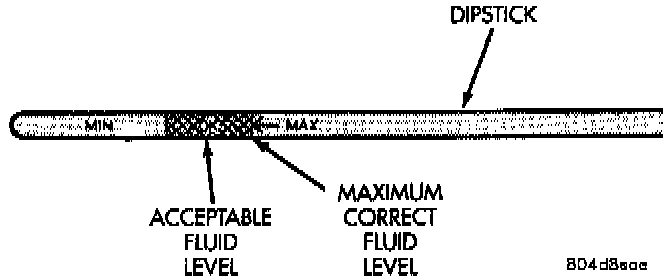
7. Remove dipstick and check fluid level as follows:
a. Correct acceptable level is in crosshatch area.
b. Correct maximum level is to MAX arrow mark.
c. Incorrect level is at or below MIN line.
d. If fluid is low, add only enough MOPAR ATF+4 to restore correct level. Do not overfill.
CAUTION: Do not overfill the transmission. Overfilling may cause leakage out the pump vent which can be mistaken for a pump seal leak. Overfilling will also cause fluid aeration and foaming as the excess fluid is picked up and churned by the gear train. This will significantly reduce fluid life.
FLUID AND FILTER REPLACEMENT
Refer to the Maintenance Schedules for proper service intervals. The service fluid fill after a filter change is approximately 3.8 liters (4.0 quarts).
REMOVAL
1. Hoist and support vehicle on safety stands.
2. Place a large diameter shallow drain pan beneath the transmission pan.
Transmission Pan:
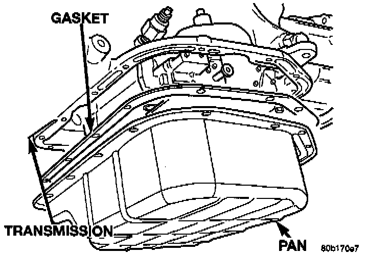
3. Remove bolts holding front and sides of pan to transmission.
4. Loosen bolts holding rear of pan to transmission.
5. Slowly separate front of pan away from transmission allowing the fluid to drain into drain pan.
6. Hold up pan and remove remaining bolts holding pan to transmission.
7. While holding pan level, lower pan away from transmission.
8. Pour remaining fluid in pan into drain pan.
Transmission Filter:
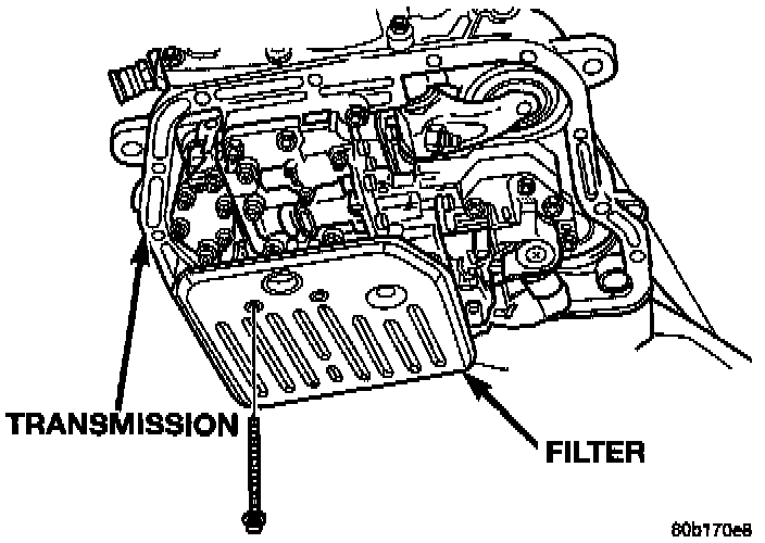
9. Remove screws holding filter to valve body.
10. Separate filter from valve body and pour fluid in filter into drain pan.
11. Dispose used trans fluid and filter properly.
INSPECTION
Inspect bottom of pan and magnet for excessive amounts of metal or fiber contamination. A light coating of clutch or band material on the bottom of the pan does not indicate a problem unless accompanied by slipping condition or shift lag. If fluid and pan are contaminated with excessive amounts or debris.
Check the adjustment of the front and rear bands, adjust if necessary.
CLEANING
1. Using a suitable solvent, clean pan and magnet.
2. Using a suitable gasket scraper, clean gasket material from gasket surface of transmission case and the gasket flange around the pan.
INSTALLATION
1. Place replacement filter in position on valve body.
Transmission Filter:
2. Install screws to hold filter to valve body. Tighten screws to 4 Nm (35 inch lbs.) torque.
3. Place new gasket in position on pan. and install pan on transmission.
4. Place pan in position on transmission.
Transmission Pan:
5. Install screws to hold pan to transmission. Tighten bolts to 17 Nm (150 inch lbs.) torque.
6. Lower vehicle and fill transmission with MOPAR ATF+4, type 9602 fluid.
TRANSMISSION FILL PROCEDURE
To avoid overfilling transmission after a fluid change or overhaul, perform the following procedure:
1. Remove dipstick and insert clean funnel in transmission fill tube.
2. Add following initial quantity of MOPAR ATF+4 to transmission:
a. If only fluid and filter were changed, add 3 pints (1-1/2 quarts) of ATF+4 to transmission.
b. If transmission was completely overhauled, torque converter was replaced or drained, and cooler was flushed, add 12 pints (6 quarts) of ATF+4 to transmission.
3. Apply parking brakes.
4. Start and run engine at normal curb idle speed.
5. Apply service brakes, shift transmission through all gear ranges then back to NEUTRAL, set parking brake, and leave engine running at curb idle speed.
6. Remove funnel, insert dipstick and check fluid level. If level is low, add fluid to bring level to MIN mark on dipstick. Check to see if the oil level is equal on both sides of the dipstick. If one side is noticeably higher than the other, the dipstick has picked up some oil from the dipstick tube. Allow the oil to drain down the dipstick tube and re-check.
7. Drive vehicle until transmission fluid is at normal operating temperature.
8. With the engine running at curb idle speed, the gear selector in NEUTRAL, and the parking brake applied, check the transmission fluid level.
CAUTION: Do not overfill transmission, fluid foaming and shifting problems can result.
9. Add fluid to bring level up to MAX arrow mark.
When fluid level is correct, shut engine off, release park brake, remove funnel, and install dipstick in fill tube.
CONVERTER DRAINBACK CHECK VALVE SERVICE
The converter drainback check valve is located in the cooler outlet (pressure) line near the radiator lower tank. The valve prevents fluid drainback when the vehicle is parked for lengthy periods. The valve check ball is spring loaded and has an opening pressure of approximately 2 psi.
The valve is serviced as an assembly; it is not repairable. Do not clean the valve if restricted, or contaminated by sludge, or debris. If the valve fails, or if a transmission malfunction occurs that generates sludge and/or clutch particles and metal shavings, the valve must be replaced.
The valve must be removed whenever the cooler and lines are reverse flushed. The valve can be flow tested when necessary. The procedure is exactly the same as for flow testing a cooler. If the valve is restricted, installed backwards, or in the wrong line, it will cause an overheating condition and possible transmission failure.
CAUTION: The drainback valve is a one-way flow device. It must be properly oriented in terms of flow direction for the cooler to function properly. The valve must be installed in the pressure line. Otherwise flow will be blocked and would cause an overheating condition and eventual transmission failure.
OIL COOLER FLOW CHECK
After the new or repaired transmission has been installed and filled, the oil cooler flow should be checked using the following procedure:
1. Disconnect the From cooler line at the transmission and place a collecting container under the disconnected line.
2. Run the engine at curb idle speed, with the shift selector in neutral.
3. If the fluid flow is intermittent or takes more than 20 seconds to collect one quart, the cooler should be replaced.
CAUTION: With the fluid set at the proper level, fluid collection should not exceed (1) quart or internal damage to the transmission may occur.
4. If flow is found to be within acceptable limits, reconnect the cooler line. Then fill transmission to the proper level, using the approved type of automatic transmission fluid.
FLUSHING COOLERS AND TUBES
When a transmission failure has contaminated the fluid, the oil cooler(s) must be flushed. The cooler bypass valve in the transmission must be replaced also. The torque converter must also be replaced. This will insure that metal particles or sludged oil are not later transferred back into the reconditioned (or replaced) transmission.
The only recommended procedure for Rushing coolers and lines is to use Tool 6906 Cooler Flusher.
WARNING: WEAR PROTECTIVE EYEWEAR THAT MEETS THE REQUIREMENTS OF OSHA AND ANSI Z87.1-1968. WEAR STANDARD INDUSTRIAL RUBBER GLOVES.
KEEP LIGHTED CIGARETTES, SPARKS, FLAMES, AND OTHER IGNITION SOURCES AWAY FROM THE AREA TO PREVENT THE IGNITION OF COMBUSTIBLE LIQUIDS AND GASES. KEEP A CLASS (B) FIRE EXTINGUISHER IN THE AREA WHERE THE FLUSHER WILL BE USED.
KEEP THE AREA WELL VENTILATED.
DO NOT LET FLUSHING SOLVENT COME IN CONTACT WITH YOUR EYES OR SKIN: IF EYE CONTAMINATION OCCURS, FLUSH EYES WITH WATER FOR 15 TO 20 SECONDS. REMOVE CONTAMINATED CLOTHING AND WASH AFFECTED SKIN WITH SOAP AND WATER. SEEK MEDICAL ATTENTION.
COOLER FLUSH USING TOOL 6906
1. Remove cover plate filler plug on Tool 6906. Fill reservoir 1/2 to 3/4 full of fresh flushing solution. Flushing solvents are petroleum based solutions generally used to clean automatic transmission components. DO NOT use solvents containing acids, water, gasoline, or any other corrosive liquids.
2. Reinstall filler plug on Tool 6906.
3. Verify pump power switch is turned OFF. Connect red alligator clip to positive (+) battery post. Connect black (-) alligator clip to a good ground.
4. Disconnect the cooler lines at the transmission.
NOTE: When flushing transmission cooler and lines, ALWAYS reverse flush.
5. Connect the BLUE pressure line to the OUTLET (From) cooler line.
6. Connect the CLEAR return line to the INLET (To) cooler line
7. Turn pump ON for two to three minutes to flush cooler(s) and lines. Monitor pressure readings and clear return lines. Pressure readings should stabilize below 20 psi. for vehicles equipped with a single cooler and 30 psi. for vehicles equipped with dual coolers. If flow is intermittent or exceeds these pressures, replace cooler.
8. Turn pump OFF.
9. Disconnect CLEAR suction line from reservoir at cover plate. Disconnect CLEAR return line at cover plate, and place it in a drain pan.
10. Turn pump ON for 30 seconds to purge flushing solution from cooler and lines. Turn pump OFF.
11. Place CLEAR suction line into a one quart container of Mopar8 ATF+4, type 9602 automatic transmission fluid.
12. Turn pump ON until all transmission fluid is removed from the one quart container and lines. This purges any residual cleaning solvent from the transmission cooler and lines. Turn pump OFF.
13. Disconnect alligator clips from battery. Reconnect flusher lines to cover plate, and remove flushing adapters from cooler lines.
ALUMINUM THREAD REPAIR
Damaged or worn threads in the aluminum transaxle case and valve body can be repaired by the use of Heli-Coils, or equivalent. This repair consists of drilling out the worn-out damaged threads. Then tap the hole with a special Heli-Coil tap, or equivalent, and installing a Heli-Coil insert, or equivalent, into the hole. This brings the hole back to its original thread size.
Heli-Coil, or equivalent, tools and inserts are readily available from most automotive parts suppliers.