Component Tests and General Diagnostics
INSPECTION
FUNCTION AND OPERATION PRINCIPLE
The Electronic Throttle Control (ETC) System consists of a throttle body with an integrated control motor and throttle position sensor (TPS). Instead of the traditional throttle cable, an Accelerator Position Sensor (APS) is used to receive driver input. The ECM uses the APS signal to calculate the target throttle angle; the position of the throttle is then adjusted via ECM control of the ETC motor. The TPS signal is used to provide feedback regarding throttle position to the ECM. Using ETC, precise control over throttle position is possible; the need for external cruise control modules/cables is eliminated.
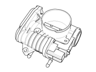
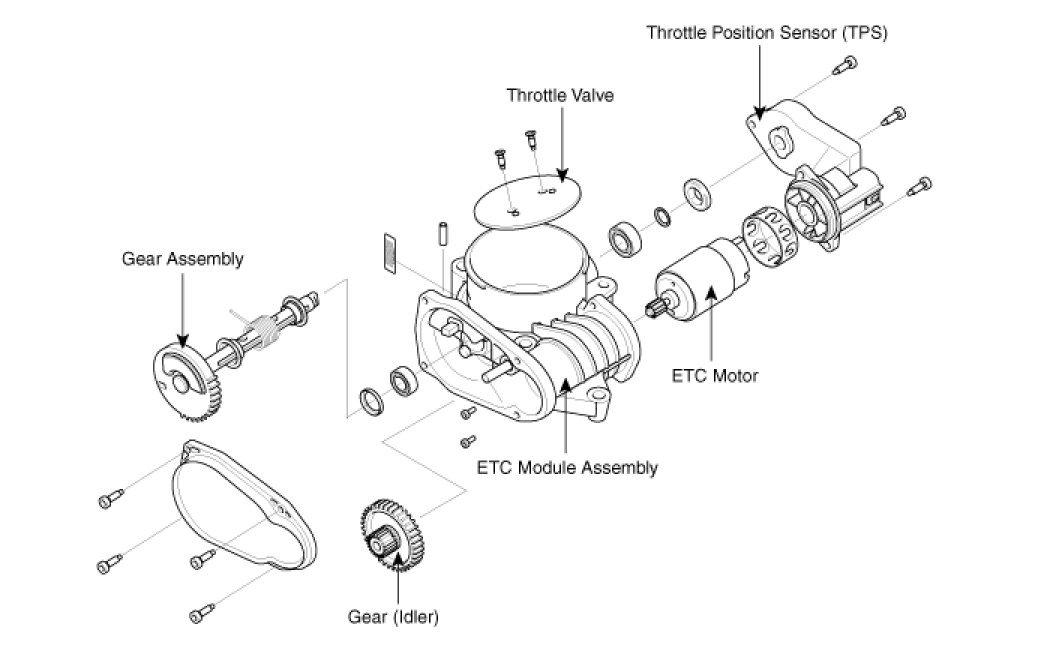
COMPONENTS

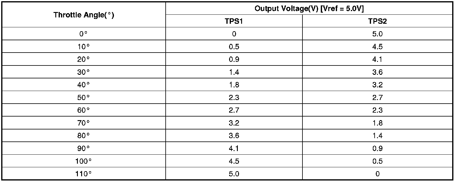
SPECIFICATION
[THROTTLE POSITION SENSOR]


[ETC MOTOR]

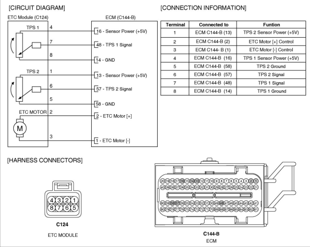
SCHEMATIC DIAGRAM
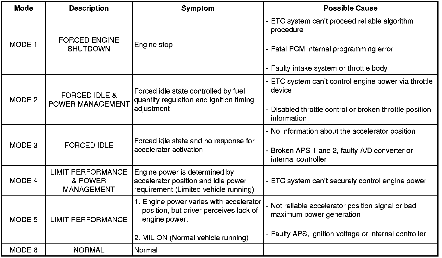
FAIL-SAFE MODE
COMPONENT INSPECTION
THROTTLE POSITION SENSOR (TPS)
1. Connect a scantool on the Data Link Connector (DLC).
2. Start engine and check output voltages of TPS 1 and 2 at C.T and W.O.T.
Specification: Refer to SPECIFICATION.
3. Turn ignition switch OFF and disconnect the scantool from the DLC.
4. Disconnect ETC module connector and measure resistance between ETC module terminals 4 and 8 (TPS 1).
5. Measure resistance between ETC module terminals 1 and 5 (TPS 2).
Specification: Refer to SPECIFICATION.
ETC MOTOR
1. Disconnect ETC module connector and measure resistance between ETC module terminals 2 and 3.
Specification: Refer to SPECIFICATION.